 Yueqing Yijin Electronics Co., Ltd.




Modular AC Contactor Install Mistakes That Leave Circuits Live
Learning how to install ac contactor hardware is less about copying a photograph and more about three separations that fail quietly: the coil circuit is not the power poles, one open pole does not make every conductor dead, and the DIN-rail clip has to carry the body before you torque anything. The sections below walk modular-panel install mistakes — not another outdoor HVAC “photograph and swap” checklist, and not a full wiring-diagram course.
Browse the live contactor range while you read. The pairing table at the end matches poles to the five SKUs currently listed there.
Coil Terminals Are Not Power Poles
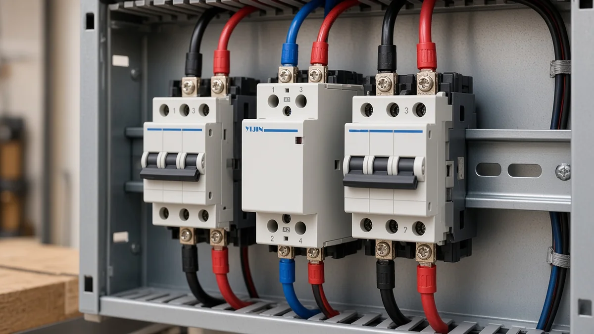
A1 and A2 only feed the magnet; the numbered power poles carry the load.
A modular AC contactor is two circuits sharing one plastic body. The electromagnet sits on its own control supply — almost always marked as Coil / A1 A2 on the frame — and the power poles open and close the load path when that magnet seats. Landing a feeder on a coil screw, or parking a thermostat lead on a power pole because it looked empty, turns into heat or a dead control call on the first start.
| Terminal role | Typical marking | What belongs there | What does not |
|---|---|---|---|
| Coil / control | A1, A2 | Rated control voltage Us from the control circuit | Load current, heater feeders, compressor leads |
| Power poles | 1/2, 1/3–2/4, or 1/3/5/7–2/4/6/8 | Conductors the design intends to switch | Unrelated neutrals or grounds used as parking |
Outdoor HVAC definite-purpose contactors often use L1/L2 and T1/T2 language for the same idea. Modular household frames on a modular AC contactor DIN rail usually print numbered poles plus the contactor coil A1 A2 pair.
Either way, treat the coil as a control circuit with its own voltage rating. Upstream breakers or fuses still clear short-circuit faults; the contactor only switches under coil control.
For AC coils, lead polarity at A1/A2 usually does not matter the way DC coils sometimes do. What does matter is that each coil conductor lands on its own terminal so the control circuit is not shorted across one screw.
When One Open Pole Still Leaves the Load Live
One opened pole does not de-energize every conductor at the load.
The install mistake that keeps showing up in field forums is finishing a neat single-pole landing and assuming the equipment is off because the contactor clicked open. On a two-hot circuit, one open pole can leave the other hot continuous through to the load. On a line-and-neutral lighting circuit, opening only one of those conductors can leave a path that still surprises a meter.
From the field: Crews who see a two-pole body sometimes assume nothing downstream is energised. Independent HVAC training notes the opposite risk on single-pole arrangements: a leg can stay live at the load even after the contactor opens — source: HVACR School on crankcase heaters and single-pole contactors. Treat “open” as “this pole opened,” then prove the rest with a meter.
Licensed-electrician discussions also separate code minimums from design practice. A controller that opens one ungrounded conductor may meet a minimum where a separate disconnect exists, while many designers still specify breaking every conductor that must go dead for service. For install work, the practical rule is simpler: if a conductor must be dead when the coil drops, that conductor needs a real switched pole.
If you are still choosing between one pole and two poles for the load type, use the dedicated comparison AC contactor 1 pole vs 2 pole rather than stretching this checklist into a selection essay.
DIN-Rail Seating Mistakes That Fail After Energizing
A half-clipped body rocks, heats terminals, and only looks installed.
Yijin’s modular pages specify DIN rail TH35-7.5. That is the common 35 mm DIN top-hat profile, also called TS35 in US shop language.
Modular install manuals for the same device class describe the mechanical sequence in plain terms: pull the retainer down, seat the contactor on the rail, push the retainer up until the body is captive.
Skip that clip and the frame can sit high on one edge. Every later screw turn then twists the housing instead of clamping copper.
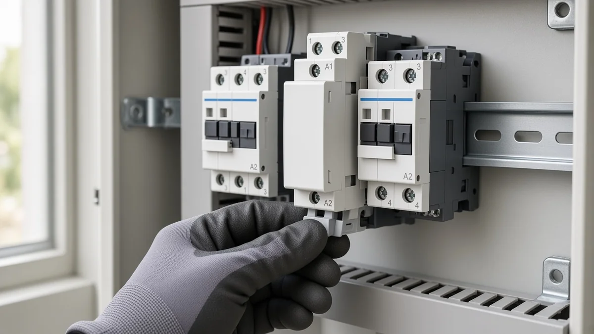
Before any conductor lands:
- Confirm the rail is the top-hat profile the device expects.
- Seat the body fully; tug lightly along the rail axis so it cannot pivot.
- Keep adjacent devices from pinching the retainer so you can still remove the contactor later.
- Isolate and verify zero energy on the circuits you will touch. Energy-control rules exist because flipping a switch is not the same as a verified dead circuit.
Capture each conductor fully in the clamp without cutting strands, and skip generic torque charts when the product page publishes none.
Wrong Coil Voltage Assumptions After a Clean Install
Coil Us is independent of the voltage the poles switch.
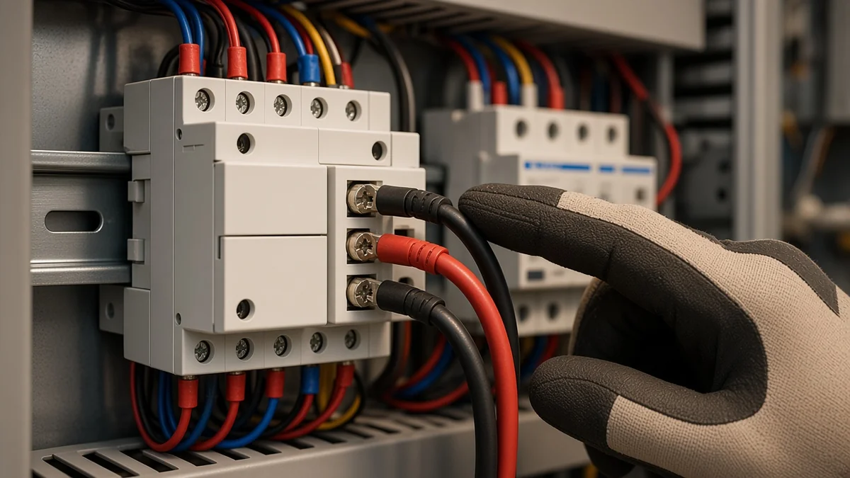
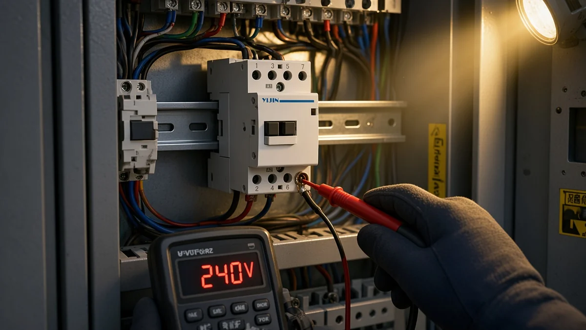
A surprisingly common failed install is perfect power wiring on a coil that never matched the control supply. The poles may be rated for a line-voltage load circuit while the magnet expects a different Us. A wrong coil voltage contactor outcome looks like silence, chatter, or a cooked winding after a short life.
Electricians on trade forums keep repeating the same split: A1 and A2 are the coil; control may come from a control transformer while the poles switch a higher utilization voltage. Match the control circuit you actually have.
Yijin’s YJC1-63 modular pages state that when rated control voltage Us is applied under the page’s ambient note, the contactor can reliably close at any voltage within (80%–110%) Us, with release voltage neither higher than 75% Us nor lower than 20% Us. That window is a first-party operating statement for that model line. Still measure what your control circuit delivers at the coil screws after the install.
If the magnet stays silent with Us present, or chatters with unstable Us, chase the control path before condemning the power poles. For a deeper control-circuit scenario map, see AC contactor not pulling in.
Shunt vs True Two-Pole: The Install That Rewires Itself Wrong
A Shunt / straight-through pole is not a second switched pole.
Some HVAC definite-purpose parts use a single switched pole plus a metal shunt — a straight bar from line to load on the second side. Van stock often carries true two-pole contactors as universal spares. Dropping a true two-pole onto a shunted original wire-for-wire can kill an always-on path that depended on the permanent bridge, including certain crankcase-heater arrangements that back-feed through compressor windings when the contacts are open.
Independent training is blunt: know what each wire did before you mirror colours onto a different mechanism. If the old device had a straight-through side, the new true two-pole will open that path unless you deliberately remap the always-hot feed to the line side per the equipment diagram.
Keep diagram literacy thin here. Upcoming modular wiring-diagram pieces own that spine. For install day, identify whether the second path was a real pole or a shunt before you land the replacement.
Which Conductors Actually Get Switched
Switch every conductor that must go dead when the coil drops.
Once coil versus poles is clear and the rail is seated, decide which conductors belong on switched poles:
- Two hot legs that must both float for service → two real poles.
- Line and neutral on a single-phase load that must both open per the design or device instructions → poles for both. Some IEC instructions tell you to break all power conductors, including neutrals.
- A conductor that must stay continuous for an always-on accessory → that path should not pretend to be a switched pole.
Skip using a power pole as a junction block for grounds. Skip parking an unused hot on an open terminal for later without a documented design. And remember the contactor switches; upstream protection still clears a bolted fault.
Choose a Modular AC Contactor After the Install Checks Clear
Prefer a true multi-pole frame when both legs must open; start with the live YJC1-63 2P when the current class matches that frame.
After the mistake classes above are closed, pick the modular frame that matches pole count and current class on the live catalogue.
Live check on 2026-09-22: the contactor category lists exactly five modular AC contactor SKUs. The live YJC1-63 / YJC-1-25 pairing is honest about which poles exist at which amp class.
| Frame | Poles available on the live site | Current class to read from H1 / nameplate |
|---|---|---|
| YJC1-63 | 1P, 2P, 4P | 63 A class on the 1P/2P/4P product titles |
| YJC-1-25 | 2P, 4P only (no 1P) | 25 A class on the nameplate / title — shared marketing copy on some pages still says “63A”; prefer the H1 and nameplate |
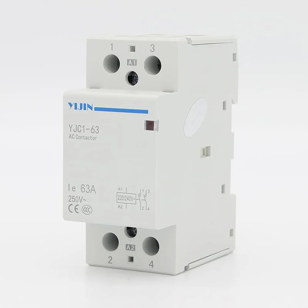
Primary recommendation for an install that must open both power conductors at the 63 A class: YJC1-63 2P Modular AC Contactor. The page documents TH35-7.5 rail mounting, normally-open conventional construction, and the Us close/release window used in the coil section above.
Choose differently when:
- The nameplate points at the YJC-1-25 current class → YJC-1-25 2P Modular AC Contactor.
- The design intentionally leaves one conductor continuous → a 1P frame exists only on YJC1-63; read the pole article before you copy an HVAC shunt habit into a panel schedule.
- Four conductors must open → use the matching 4P SKU on the same current frame.
The pages publish no UL listing, terminal torque, or millimetre outline drawings. Treat those silences as silences on install day.
FAQ
What do A1 and A2 do when I install an AC contactor?
They are the coil supply terminals. Apply the rated control voltage Us across A1 and A2 so the electromagnet can seat the power poles. They are not spare power terminals.
Why is my load still live after the contactor opens?
Because an open pole only opens that pole. On multi-wire circuits, another hot or a neutral path can remain continuous unless it also lands on a switched pole or a separate disconnect.
How should a modular contactor sit on a DIN rail?
On a TH35-7.5 top-hat rail, pull the retainer, seat the body, and lock the retainer so the housing cannot pivot when you tighten terminals.
Why won’t a newly installed contactor pull in?
Check Us at the coil screws against the coil rating first. Wrong coil voltage, an open control string, or unstable Us produce dead installs even when the power wiring looks perfect.
Can I replace a shunted single-pole with a true two-pole the same way?
Not wire-for-wire by default. A shunt is a permanent bridge; a true second pole opens that path and can disable always-on accessories unless you remap per the equipment diagram.
Which Yijin modular contactor pole and current pairs exist?
Five live SKUs: YJC1-63 in 1P/2P/4P; YJC-1-25 in 2P/4P only. Prefer H1/nameplate current over reused marketing sentences that still say sixty-three amperes on some twenty-five-ampere pages.
Is a contactor a short-circuit protective device?
No. It switches load current under coil control. Keep coordinated upstream short-circuit protection.
Do I always need to break the neutral?
Only when the design or the device instructions require that conductor to open with the coil. Some IEC contactor instructions call for breaking all power conductors; U.S. practice for a given assembly still follows the equipment diagram and applicable rules for that installation.
References
- Household modular contactor standard catalogue entry — standards body record for household and similar electromechanical contactors.
- Contactor — Wikipedia — coil versus contacts; short-circuit interruption boundary.
- DIN rail — Wikipedia — top-hat rail and module-width practice.
- Contactor construction, operation, application and selection — independent technical explanation of A1/A2 and power terminals.
- Crankcase heaters and single-pole contactors — independent training on single-pole live-leg and shunt/2P swap risks.
- Control of hazardous energy — eCFR lockout text — energy isolation before servicing.
- Why use a two-pole contactor on a single-phase motor? — licensed-electrician forum on one-leg vs both-legs practice.
- Contactors / coil voltage — electrician forum on matching coil Us at A1/A2.
Humanizer audit: PASS — second pass cut meta “this article” framing, reduced boundary stacks, and kept Us/pole facts without invented torque or UL claims. No new facts added beyond research/brief.
Draft Agent ID: YIJINELE-DRAFT-20260922-02