 Yueqing Yijin Electronics Co., Ltd.




How to Read a Phase Sequence Relay Wiring Diagram
A phase sequence relay wiring diagram is a terminal map: it shows supply marks, load or output marks, and any printed control or monitoring contacts, and it stops before it invents wire size or listing status. The sections below walk a US panel drawing the same way a field reader should — supply first, then output, then contacts when printed, then the blank edge of the sheet.
Field meter checklists and detector-circuit builds belong on sibling articles, not here. Browse the live Transfer Switch / Phase Sequence Converter range while you compare marks. IEC or enterprise-standard wording on a product page is a page label, not a UL Listed or NEC approval claim.
When a Phase Sequence Relay Diagram Shows Up in a Panel Package
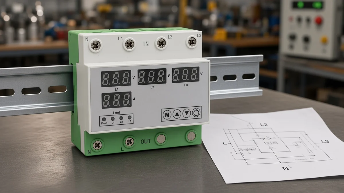
The sheet is a terminal map for sequence monitoring or conversion — not a full install ticket or a field meter checklist.
Estimators and electricians usually meet it as a small block beside a motor starter, a three-phase feeder, or a dual-source panel note.
Resistive heaters may ignore phase order. Motors reverse when any two phases swap, and that reverse can damage driven equipment even when line-to-line voltages still look normal.
The drawing’s job is narrow. It tells you which screws belong to the sensed supply, which marks belong to the load or output path when they are drawn, and which small contacts feed a coil or lamp when those contacts are printed.
It does not replace the nameplate on the device in your hand. It also does not replace a rotation meter when the job is a live field check — that checklist lives on How to Test Phase Sequence.
From the field: Mobile and plug-in equipment crews often swear a feed is already clockwise. Sequence and phase-quality relays still earn their keep on that equipment because the claim and the conductor order are not the same thing. — source: community field reports on temporary three-phase feeds (research extract; not linked in References).
Read the Supply Marks First: L1, L2, L3, and N
Start at L1/L2/L3 in the printed order; check whether Neutral N is on the sheet before landing a fourth conductor.
On a classic phase sequence monitoring relay sheet, the first block is almost always the three-phase sensing input. Marks may read L1, L2, L3 or R, Y, B.
Buyers searching phase failure relay wiring still start at those L1 L2 L3 terminals before anything else.
Those letters name the order the manufacturer expects at the sensing terminals. They are not a free rename of a whole plant’s ABC/ACB habit. Naming myths belong on the ABC and ACB sibling; here you only match the printed order on this sheet.
Some sheets are three-wire. Others are four-wire and print N.
A 3-wire diagram and a 4-wire diagram are not interchangeable. If N is missing from the drawing, do not invent a neutral landing from habit.
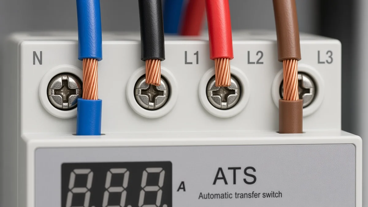
Datasheet notes sometimes share power and sensing on the same marks. For example, L1 and L3 also feeding the relay’s internal supply.
Read that note when it is printed. The same class of sheet may warn against placing the relay on the load side of an inverter.
Those warnings travel with the printed sheet, not with a generic internet habit.
Find the Load or Output Marks on the Sheet
Load/output marks show where power leaves; a classic relay may only show contact symbols, while a conversion switch shows power poles.
This is where many readers go wrong. On a monitoring-relay diagram, the “output” is often a small changeover contact that sits in a contactor coil path.
The motor feeder still runs through a contactor or other switching device. The relay contact is not the motor feeder itself.
On a reverse-protection sketch built from a sequence relay plus two interlocked contactors, the sheet may show phase swaps on the contactor power poles. That is a different map from a dry-contact-only relay.
Read which device actually carries the load current.
On an automatic phase sequence conversion switch sheet, expect power-path marks for inputs and outputs. That includes four-in / two-out language when the catalogue device monitors multiple inputs and selects an output.
That is still a diagram literacy job: find the supply side, find the load side, then stop inventing unmarked conductors.
Read Control vs Monitoring Contacts Only When Printed
11/12/14-style blocks are control or monitoring contacts for a coil or lamp path — not the motor feeder itself.
Changeover contacts 11/12/14 are the common printed set on many monitoring-relay drawings: 11 as common, 12 as normally closed, and 14 as normally open.
Other families use dual contact blocks. When the sheet uses a closed-circuit principle, healthy sequence keeps the output relays energised and a sequence fault or phase failure drops them out.
| Mark group on the sheet | Typical job on the drawing | What it is not |
|---|---|---|
| L1 / L2 / L3 | Sensing (and sometimes relay power) | A free rename of plant ABC labels |
| Neutral N | Fourth wire on 4-wire sheets | Required on every 3-wire sheet |
| Changeover contacts 11/12/14 | Control or monitoring changeover | Motor power poles |
| Contactor coil path | Where the contact often lands | Proof the relay swaps phases alone |
| Blank margin | End of the printed instruction | Missing wire size or listing status |
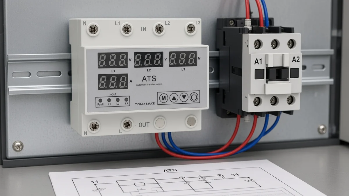
Hobby how-tos often insert the relay’s normally open path into a starter push-button circuit. They may light an indication lamp from the normally closed path.
That is contact literacy, not permission to treat the contact block as a three-phase feeder.
If the sheet is silent on contact numbers, do not invent an 11/12/14 block from another brand’s datasheet.
Stop Where the Wiring Diagram Stops
The sheet does not size the wire, prove UL/NEC, or replace a rotation meter checklist.
A wiring diagram shows relative terminal arrangement. It is not an ampacity table, a torque chart, or a listing certificate.
US readers still need the local code path and the nameplate in hand after the read.
Also stop before importing sibling jobs into this URL.
Detector-circuit physics lives on 3 Phase Sequence Detector Circuit. Meter PASS/FAIL steps live on the test article.
Here the useful end of the instruction is the last printed mark.
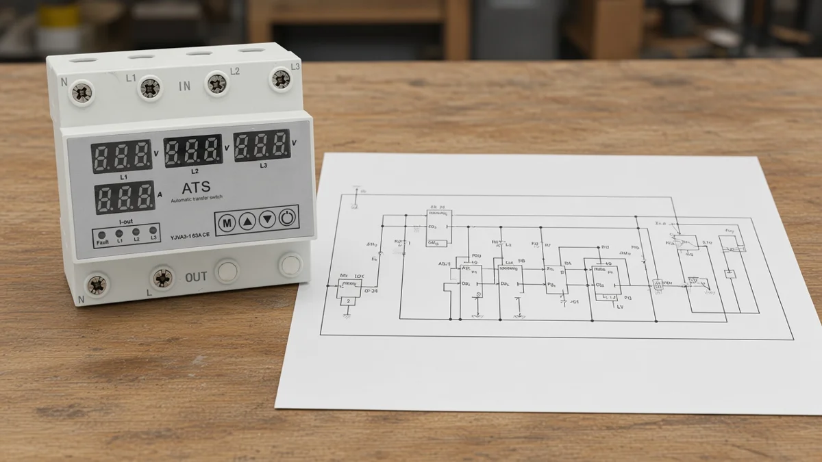
| If the sheet is silent about… | Do not invent… |
|---|---|
| Wire size or torque | AWG, Nm, or ferrule rules |
| Upstream short-circuit device | Breaker or fuse rating |
| UL or NEC marks | A listing or code approval claim |
| Field test method | A meter PASS/FAIL checklist |
| Contact numbers | Another brand’s 11/12/14 map |
When the Sheet Is a Conversion Switch, Not a Relay-Only Contact Map
Yijin’s live match detects a sequence fault and switches the power path — it is not a dry-contact-only relay SKU.
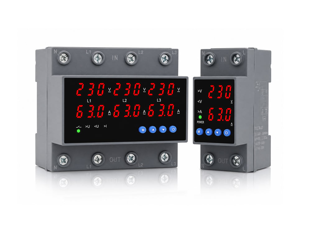
Search language still says “phase sequence relay.” On yijinele-group.com, the Transfer Switch category (browser title Phase Sequence Converter) lists manual YJFT families and the YJVA3-1 3P+N four-in-two-out automatic phase sequence conversion switch.
There is no classic phase-sequence-relay-only SKU that only monitors and outputs dry contacts.
That honesty changes how you read the sheet. Expect power input and output marks, a printed Wiring diagram section on the product page, and precautions about Neutral N and a Companion MCB — not only an 11/12/14 coil interlock.
The page states that on a phase-sequence fault the device automatically detects and switches to the normal phase-sequence power supply output. Overvoltage, undervoltage, overcurrent, and output phase sequence are user-settable.
Read those as page-stated behaviours for this model, not as a UL proof.
Choose the YJVA3-1 Conversion Switch When You Need Detect-and-Switch
Select YJVA3-1 when the job needs automatic conversion after a sequence fault, within the printed 3P+N and AC230V window.
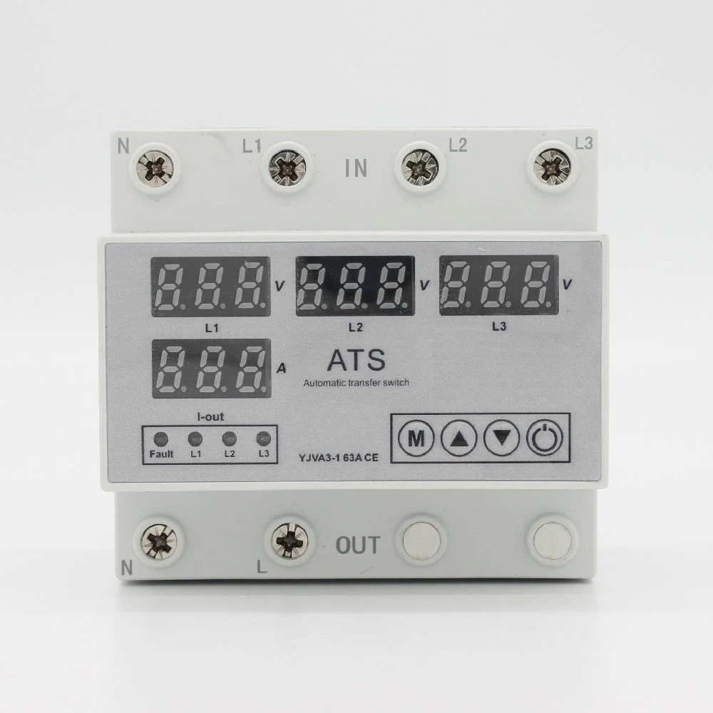
After you finish the terminal-map read, open the live product when the application needs detect-and-switch on the power path rather than a dry-contact interlock alone.
| Printed item | YJVA3-1 page value | Diagram-reading use |
|---|---|---|
| Poles | 3P+N | Match a four-conductor supply map when N is required |
| Rated operational voltage | AC230V | Keep control expectations inside the printed class |
| Working current | 3A~63A adjustable (default 63A) | Compare load current to the protection setting |
| Frequency | 50Hz/60Hz | Confirm supply frequency class |
| Undervoltage cut-off | 140V-200V (default 170V) | Page-adjustable window |
| Overvoltage cut-off | 240V-300V (default 270V) | Page-adjustable window |
| Phase sequence switching detection time | OFF-1s~500s (default 10 seconds) | Delay after a sequence fault before switching |
| Power-on delay | 1s-500s (default 10 seconds) | Delay at energisation |
| Max line voltage note | should not exceed 330VAC | Hard page precaution |
| N wiring | N must be reliable; N is a straight-through wire without disconnection | Do not treat N as a switched pole |
| Short-circuit partner | Needs a companion miniature circuit breaker | The conversion sheet does not invent that breaker |
Manual YJFT transfer switches in the same category change source under handle operation. Their pages do not state automatic phase-sequence detection, so do not read them as a drop-in for a detect-and-switch diagram.
FAQ
How do you read L1, L2, and L3 on a phase sequence relay wiring diagram?
Read them as the sensing order the sheet prints. Land the three phases on those marks in the labelled order. Do not treat the letters as a free rewrite of a whole plant’s ABC naming scheme.
What do terminals 11, 12, and 14 mean?
On many monitoring-relay sheets they are a changeover contact set used in a control or indication path. Common is often 11, with 12 and 14 as the normally closed and normally open legs. They are not the three-phase motor feeder.
Does every phase sequence relay diagram need a neutral?
No. Some sheets are three-wire; others print Neutral N for a four-wire supply. Follow the printed variant instead of inventing a silent N.
Can a phase sequence relay reverse the phases by itself?
A classic monitoring relay usually opens or closes a contact. Reverse-protection sketches that actually swap phases use contactors or a conversion device on the power path.
Is a phase sequence relay the same as a conversion switch?
Not on this catalogue. A monitoring relay typically senses and signals, while a conversion switch such as YJVA3-1 detects a sequence fault and switches the power path.
How does the diagram connect to a contactor coil?
On many monitoring-relay drawings, the changeover contact sits in series with the contactor coil so a sequence fault drops the starter. The contactor still switches the motor.
Does Yijin sell a classic phase sequence relay?
No. The live Transfer Switch / Phase Sequence Converter category lists YJFT manual transfer families and the YJVA3-1 conversion switch, with no relay-only dry-contact SKU.
Which YJVA3-1 marks matter when you leave the relay-style sheet?
Start with 3P+N, AC230V, the adjustable current window, the sequence switching detection time, the power-on delay, the N through-wire note, the Companion MCB requirement, and the maximum line voltage note of 330VAC.
References
- Three-phase electric power — Wikipedia — why L1/L2/L3 order matters for motor rotation.
- Wiring diagram — Wikipedia — a terminal map shows connections; it does not invent wire size or listing status.
- Phase sequence indicator types and working principles — Electrical4U — sensing versus indication literacy for sequence devices.
- EEVblog forum: simple phase sequence detector caveats — detection/indication is not the same job as switching the power path.