 Yueqing Yijin Electronics Co., Ltd.




What a 3 Phase Sequence Detector Circuit Detects, and What Acts on It
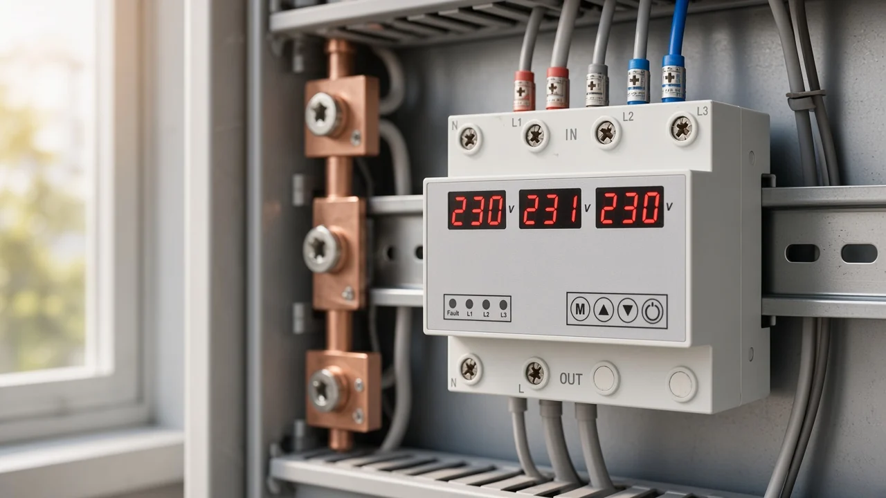
A 3 phase sequence detector circuit senses which of the three line voltages reaches its peak first, second and third, then signals whether that order is the forward one the connected equipment expects. It reads rotation. It changes nothing by itself, and that gap between reading and acting is where a search for a schematic usually turns into a buying question.
What a 3 Phase Sequence Detector Circuit Actually Detects
The measured property is order, not magnitude. Phase sequence is the manner in which the voltage of each phase reaches its peak value, so a detector compares arrival times rather than volts.
Because all three voltages are equal in a balanced system, a voltmeter alone cannot answer the question. The circuit has to create some deliberate asymmetry — a capacitor branch, a timing reference, an isolated pulse — and read the result.
Engineers label the forward order ABC and the reverse order ACB. Field technicians usually call the same property phase rotation, and both terms describe the same thing: the direction in which the rotating field will turn.
- Forward order, written ABC, is also called positive sequence and turns a machine the intended way.
- Reverse order, written ACB, is negative sequence and turns the same machine backwards.
- Swapping any two of the three conductors flips the order, which is why a rewired panel can look identical and behave the opposite way.
Why Rotation Order Decides Motor Direction and Source Paralleling
Rotation order matters because it decides mechanical direction. Phases must be connected in the correct order to achieve the intended direction of rotation of three-phase motors, and pumps and fans do not work as intended in reverse.
An induction motor gives away the fault immediately. A conveyor runs backwards, a pump loses head, a compressor may be damaged in seconds — all from a phase reversal that no voltage reading would reveal.
The second consequence is heavier. Two sources of three-phase power must not be connected in parallel unless they have the same phase sequence, otherwise the interconnection will behave like a short circuit and excess current will flow. Any board fed from two supplies inherits that rule.
Important: rotation cannot be assumed stable just because it was correct at handover — one electrician described a site where “there was no consistency in phasing at the facility or in the motor windings” — Electrician Talk rotation-meter thread.
Lamp-and-Capacitor Detection: The Classic Static Indicator
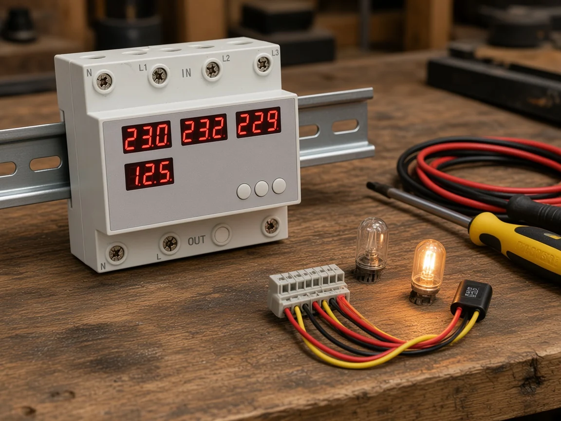
The passive family is the oldest and still the easiest to reason about. Two phases feed two lamps, the third phase reaches the lamps’ common junction through a capacitor, and the capacitive branch shifts one leg enough to unbalance the two lamp voltages.
You read the result by comparing brightness. For one order, a particular lamp glows noticeably brighter; reverse the order and the other lamp takes over. Static indicators of that type use lamps whose brightness depends on the phase sequence, with some variants using capacitors and neon lamps.
Teaching labs formalise the same trick with chosen component values. One university power-systems exercise analyses the network with a capacitance of 50 µF and several resistance values compared against the capacitive reactance magnitude, to find which combination gives the largest voltage difference between the abc and acb cases.
The rotating cousin of this circuit is a small motor in a case. Its disc turns clockwise for one order and counter-clockwise for the other, which is what most hand-held instruments still show behind their window.
Zero-Crossing and Logic Detection in Solid-State Designs
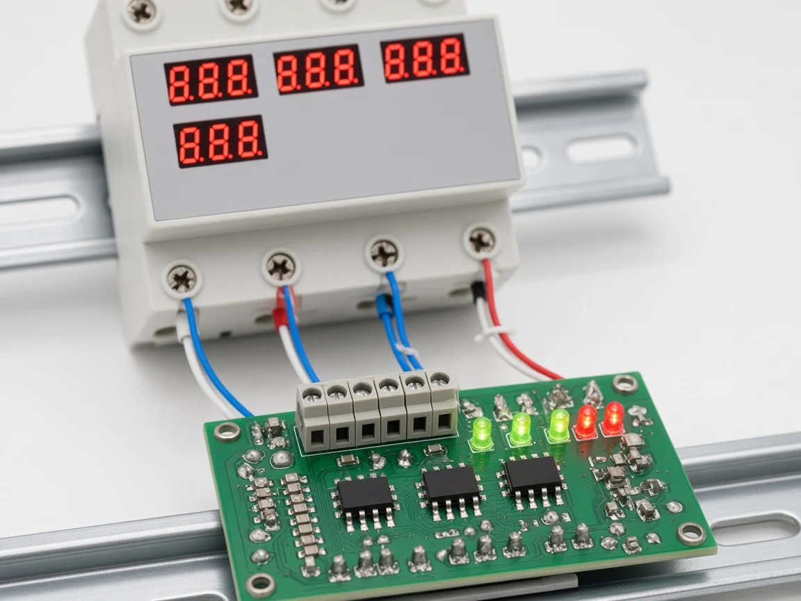
Digital detection replaces brightness with timing. Each phase is stepped down through a small transformer or an opto-coupler to produce a clean pulse at every zero crossing, and logic then measures which pulse arrives between which pair.
One published open build makes the method explicit: three optical isolators provide zero detection, and the two time differences between the phase crossings are enough to recover the phase angles. A documented academic prototype covering a supply range of 200 volts to 500 volts rectified the stepped-down phases, timed the positive-to-negative half-cycle crossings in a microcontroller, and drove LEDs for clockwise or anticlockwise order.
The same signal chain answers a second question for free. If a pulse train disappears entirely, the circuit sees phase loss rather than a rotation change, which is why commercial units usually indicate both faults from one measurement.
That approach is not new or experimental. A 1976 patent titled “Phase sequence detector for three-phase AC power system” used flip-flop logic on the phase inputs, and its classifications cover indicating phase sequence and preventing switch-on in an undesired condition — detection tied to inhibition, from the start.
Detector Circuit, Phase Sequence Indicator, or Phase Sequence Relay?
Three device classes answer three different questions, and buyers routinely price one against another by mistake. A detector circuit is the sensing core; a phase sequence indicator packages it for a person to read; a phase sequence relay packages it for a control system to read.
| Device class | What the reader gets | Output | Typical use |
|---|---|---|---|
| Detector circuit (board level) | Sensing core only, no enclosure or rated interface | Logic level or an on-board lamp | Embedded inside OEM equipment such as compressor controls |
| Phase sequence indicator / rotation tester | Hand-held instrument read by an operator | Visual only — disc, lamps or LEDs | One-off commissioning check, a quick phase sequence test before energising a motor |
| Phase sequence relay | Panel device monitoring the supply continuously | Dry contact for a contactor, PLC or alarm | Permanent monitoring where another device must react |
| Phase-sequence conversion switch | Panel device that senses and reroutes the supply | Switched output to the load | Sites where the load has to stay powered through a rotation or voltage fault |
Instrument behaviour differs inside the indicator class too. A rotation tester may contain a miniature three-phase motor, or a pair of lamps with an internal phase-shifting network, or a residual-magnetism sensor read while the motor shaft is turned by hand on a de-energised machine.
Trade forums show how easily the classes blur. Members of one electrician thread separated rotation testers from motor-rotation testers with a blunt “Big difference in price”, while another admitted “I almost never use one, I just bump it” — a habit that authority guidance warns against, since energising a machine to watch it turn may be impractical or harmful.
What a Discrete Detector Circuit Cannot Do in a Live Panel
Getting the logic right is the easy half. A beginner posted a NAND-gate design with a simple wish — “All I required was to have LED on when phase sequence was RYB and Led off when any another phase sequence arrives!” — and the reply exposed everything that separates a schematic from a device.
The reviewer accepted the gate section as a working detector, then found the transistor and LED stage “entirely bogus”, passing far too much current for a 30 mA LED. Worse, the logic used Neutral as its supply reference and left the phase inputs non-isolated, which the reviewer called unsafe once that output goes to other low-voltage circuits.
Three practical limits follow from that critique, and they apply to any home-built board:
- Isolation. Line-referenced logic is acceptable behind a sealed lamp box and dangerous the moment it feeds a controller.
- Interfacing. Panels expect a dry contact with a stated rating, not a bare logic pin.
- Enclosure and mounting. A board without a DIN rail housing, terminal ratings and ingress protection has nowhere to live in a real board.
None of that stops a detector circuit from being the right answer for an OEM designing its own equipment — one granted patent covers exactly that pattern, with optical couplers per phase pair and rising-edge logic reporting an abnormal three-phase input to a compressor controller. It does mean a buyer who wants panel protection is shopping for a packaged device, not a schematic.
Where Yijin’s Live Catalogue Fits: Conversion, Not Detection Only
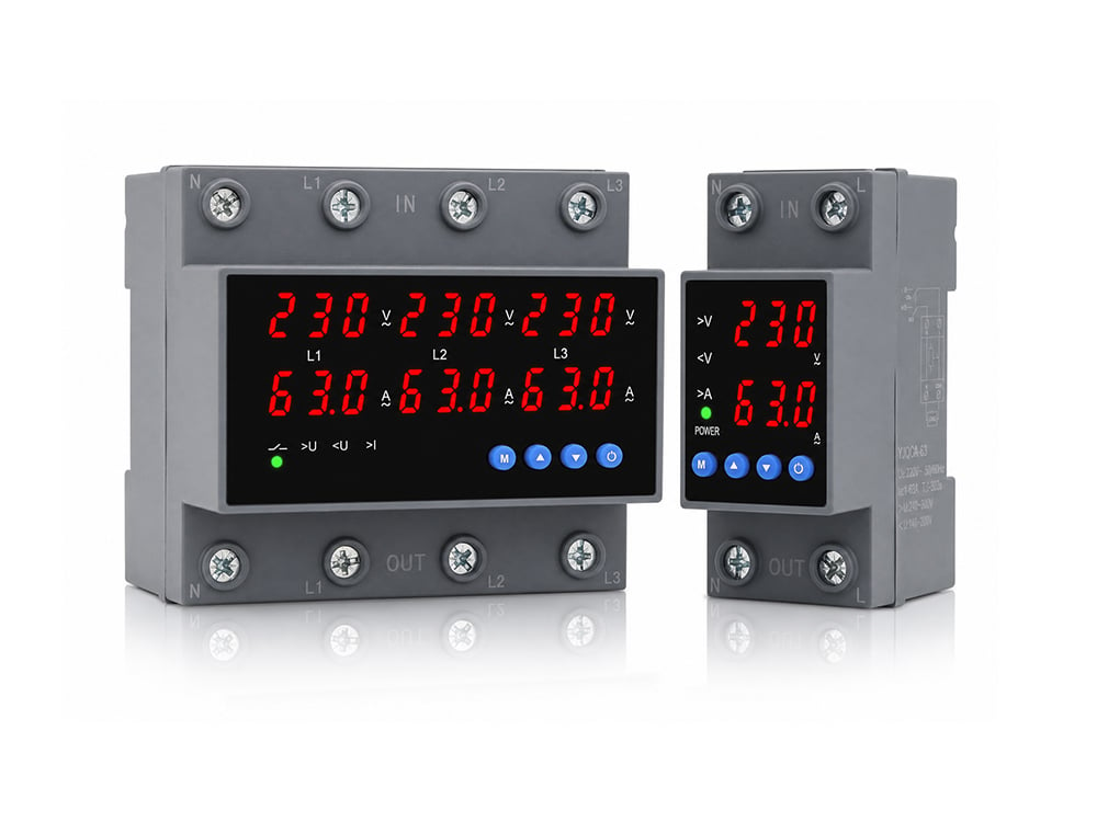
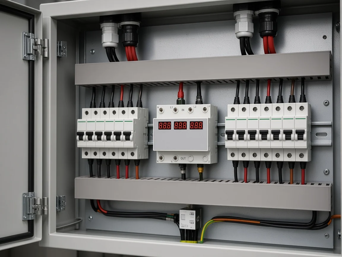
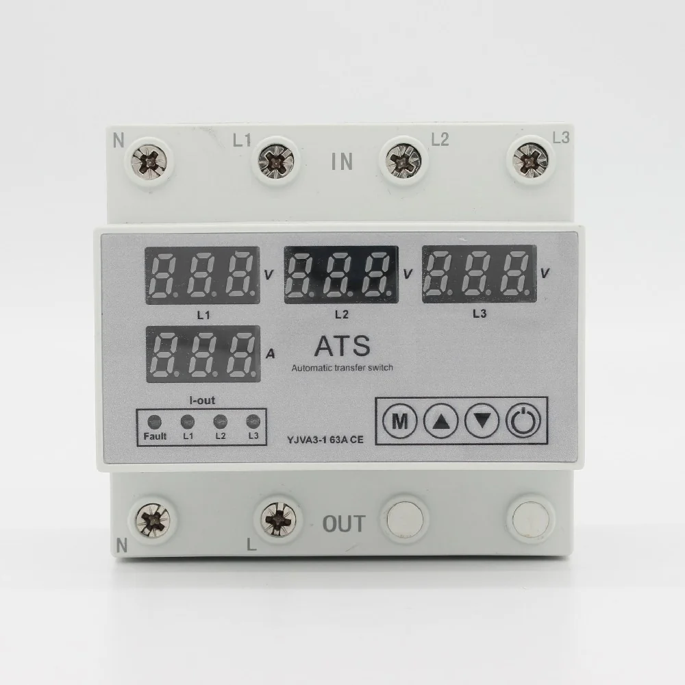
Yijin’s live answer to this topic is a switching device, not a detector board and not a test instrument. The YJVA3-1 3P+N four-in-two-out automatic phase sequence conversion switch sits in the Transfer Switch category, whose live listing is titled Phase Sequence Converter.
Its page describes the behaviour plainly: the 4-in-2-out design monitors multiple power inputs simultaneously and selects the appropriate power output based on the set parameters, and when there is a phase sequence fault in the line the switch automatically detects it and switches to the normal phase sequence power supply output. After a self-set delay it reconnects without manual operation.
| Printed parameter (YJVA3-1 page) | Page value |
|---|---|
| Poles / connection | 3P+N, up and down or down and up and out |
| Rated operational voltage | AC230V, maximum line voltage should not exceed 330VAC |
| Rated working current | 3A~63A adjustable (default 63A) |
| Rated working frequency | 50Hz/60Hz |
| Undervoltage action cut-off | 140V-200V adjustable (default 170V) |
| Overvoltage action cut-off | 240V-300V adjustable (default 270V) |
| Phase sequence switching detection time | OFF-1s~500s adjustable (default 10 seconds) |
| Electrical and mechanical lifespan | More than 100000 times |
| Installation | Standard rail installation |
| Short-circuit protection | Page states the product needs to be paired with a miniature circuit breaker |
Two honest boundaries belong beside that table. The same category also lists the manual YJFT-63 and YJFT-125 families, whose pages describe handle operation with I-0-II source indicator lights and durability testing to the requirements of IEC 60947-3, with rated voltage 230/400V~ and rated current 63A/125A — source changeover under human control, with no rotation sensing described in the page text.
The second boundary is scope. Nothing on the reviewed pages makes the conversion switch a substitute for a commissioning instrument, and the page itself sends short-circuit protection to a companion breaker.
Choose YJVA3-1 When You Need Detection Plus Automatic Switching
Pick the switching device when the answer to “what happens next” has to be automatic. If your load must keep running through a rotation or voltage fault on one incoming feed, the YJVA3-1 automatic phase sequence conversion switch is the live model whose page states detection followed by switching to a normal phase sequence output.
It is the wrong purchase in three cases, and saying so is cheaper than a return. A commissioning engineer who needs a hand-held rotation reading should buy an instrument; a designer who needs a signal for a PLC should look for a monitoring relay with contacts; a panel without upstream short-circuit protection still needs that breaker regardless.
Buyers comparing the manual families alongside it can browse the full Transfer Switch category, where the YJFT ranges sit next to the conversion switch. If a project needs a pole count or current rating that is not listed, the contact form on the product page is the practical route to ask.
FAQ
How do you run a phase sequence test with a multimeter?
You can compare pairs rather than read order directly: phase sequence of two sources can be verified by measuring voltage between pairs of terminals, where terminals with very low voltage between them share a phase and pairs showing a higher voltage sit on different phases. That confirms identity between two supplies, not the ABC order of one supply, which is why a dedicated rotation instrument still earns its place.
Can a detector circuit tell ABC from ACB without a motor?
Yes — that is the whole point of the lamp-and-capacitor arrangement. The capacitor creates an artificial imbalance so one lamp is brighter for one order and the other lamp is brighter for the reverse, with no rotating machine involved.
Is it safe to build a DIY phase sequence detector circuit?
Only under narrow conditions, and community review is blunt about why. A working gate-level detector was still judged unsafe because its logic referenced Neutral and its phase inputs were non-isolated, which stops being acceptable as soon as the output leaves a sealed lamp box and feeds other low-voltage circuits.
What happens if two three-phase sources have opposite rotation?
Paralleling them behaves like a short circuit and excess current flows, so sources must match before they can ever be connected at the same time. On a two-feed board this is why the switching logic must transfer between sources rather than bridge them.
Does a phase sequence indicator show phase loss as well?
Many packaged devices do, because the same measurement carries both facts. If one phase pulse disappears the sensing chain sees phase loss, while a change in pulse order signals reversal — commercial units commonly indicate the correct order in green and either fault in red.
How quickly should a phase-sequence fault be acted on?
That is a settings question, not a universal number. On the YJVA3-1 page the phase sequence switching detection time is adjustable from OFF and 1s to 500s with a default of 10 seconds, so the delay is matched to the load rather than fixed by the device.
Do manual transfer switches check rotation before you switch?
Not according to their page text. The YJFT-63 and YJFT-125 families are handle-operated switches with I-0-II indicator lights showing which source is live, so the rotation decision stays with the person operating the handle.
Which YJVA3-1 parameters matter most for rotation faults?
Start with the detection time, then the voltage windows. The printed undervoltage cut-off of 140V-200V and overvoltage cut-off of 240V-300V decide when the module treats a feed as unhealthy, while the detection time decides how long a rotation fault must persist before the output moves.
References
- Three-phase electric power — phase sequence and testing methods
- NJIT ECE 449 Power Systems Laboratory: phase sequence measurements
- Electrical4U: phase sequence indicator types and working principles
- GeeksforGeeks: phase sequence indicator components and operation
- EEVblog forum: review of a simple NAND-gate phase sequence detector