 Yueqing Yijin Electronics Co., Ltd.




How to Test Phase Sequence in the Field
You settle how to test phase sequence by confirming all three phases are present, then reading whether the order is the expected ABC-type (clockwise) rotation or the reverse. The handheld meter or lamp method only reports that order — it does not rewrite the feed. The sections below cover prep, a PASS/FAIL meter checklist, lamp-method limits, and when a live Yijin conversion switch fits after the test.
What a Field Phase-Sequence Test Is Deciding
The test decides which of the two three-phase orders is present at the clips — not whether a letter label on a drawing is “correct.”
Phase sequence (also called phase rotation) is the order in which the three phase voltages reach their peaks. For a three-phase system there are only two possibilities.
Crews often write them as ABC / ACB, or as clockwise versus counterclockwise on a phase rotation meter. That one-line distinction is enough here; a separate article owns the naming myths around ABC and ACB phase sequence labels on drawings.
The reading matters because an induction motor reverses when the supply order reverses, and paralleling two sources with mismatched sequence is hazardous. The field job is narrower: prove the order at this test point before you energize equipment that cares about direction.
Prep Before You Clip On: Dead Trace vs Live Indication
Trace and label when the circuit is dead when you can; treat live indication as qualified work with a CAT-rated tool.
A dead check asks whether L1, L2, and L3 stay on matching terminals through joints, isolators, and boards. That is visual and continuity work with the supply locked out.
A live check asks what rotary field is actually present after energizing. Training material often stresses that those two jobs get mixed up — one proves conductor identity through the install; the other proves the live order at a point.
Before any live clips:
- Confirm you are qualified for the voltage and environment.
- Use a phase sequence indicator or phase rotation meter rated for the system category and voltage.
- Inspect leads and clips for damaged insulation.
- Plan where you will de-energize if you must swap two phase conductors after a reverse reading.
- Photograph or tag the as-found connections so the next person inherits the same designation.
Do not treat a conversion switch or transfer device as your lockout means while you probe.
Handheld Meter PASS/FAIL Checklist
Confirm all three phase-presence lights, then read CW vs reverse — stop if any presence lamp is dark.
Most handheld procedures share the same PASS/FAIL spine, whether the faceplate says L1-L2-L3 or R-S-T:
- Isolate if your procedure requires attaching leads cold, then land the three color-coded clips on the three line conductors.
- Energize only for the measurement window your safe-work plan allows.
- Confirm the three phase-presence indicators are all on.
- Read the sequence indication: clockwise / L1-L2-L3-type PASS for the expected order, or counterclockwise / reverse FAIL for the opposite order.
- If reverse, de-energize, lock out, swap any two phase conductors, retest, then label the as-left order.
| Reading | What it means | Action |
|---|---|---|
| All three presence lamps on + CW / L1-L2-L3 | Expected sequence at the clips | PASS — tag the conductors to match the leads |
| All three presence lamps on + CCW / reverse | Opposite rotation | FAIL — de-energize, swap any two phases, retest |
| Any presence lamp dark | Open or missing phase at a clip | STOP — do not trust the sequence lights; find the open phase |
| Sequence light on but one clip may be on N | False confidence risk | Recheck that every clip is on a live phase |
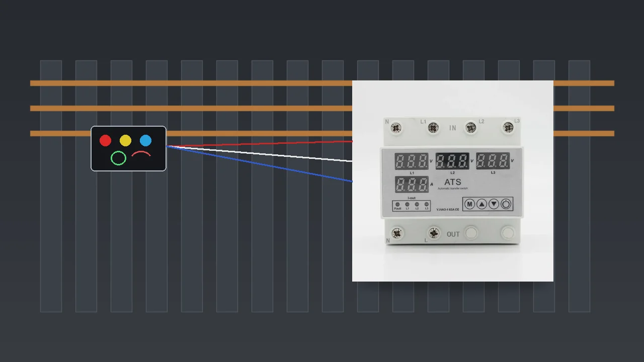
Important: Some rotary indicators can still show a rotation direction if one probe sits on the neutral instead of a phase. Confirm three live phases before you treat the arrow as a PASS. (Source: Fluke 9040 Phase Rotation Indicator Users Manual — rotary indicator warning.)
If your instrument has a separate motor-rotation mode, that is a different test on a de-energized machine. Do not mix the supply-sequence reading with a hand-spun motor check in the same step.
Lamp Method: What Brightness Can and Cannot Prove
Relative lamp brightness reports sequence; it still only indicates and does not switch the feed.
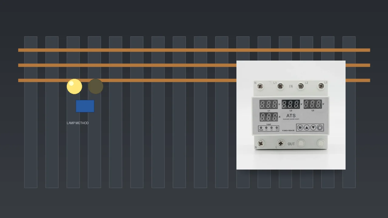
A classic static phase sequence indicator uses two lamps and a capacitor (or inductor) as an unbalanced load. Because the reactive leg shifts the voltages, one lamp runs bright and the other dim for a given order.
Swap two phases and the bright/dim pattern reverses. Neon variants may show one lamp on and the other dark.
That is useful when a commercial meter is not on the truck and a competent person builds or uses a known lamp harness. It answers the same binary question as the meter: which of the two orders is present. It does not tell you which drawing letter is “right,” and it does not change the conductors for you.
Keep the circuit theory thin here. If you need detector-board families versus relays versus switching devices, use the companion piece on a 3 phase sequence detector circuit.
What the Test Cannot Do: Indication Is Not Switching
The meter does not rewrite conductors, protect the load, or guarantee a VFD load-side reading.
A PASS/FAIL sequence test is an indication. After a FAIL you still have to de-energize and rearrange two phase leads, or leave the as-found reverse tagged for the next crew.
The instrument does not become a transfer device. It does not clear undervoltage, overvoltage, or overcurrent on the feed. It does not isolate the circuit for repair.
Two common field traps sit outside the meter face:
- Bumping a motor to “see which way it spins” can work on tolerant loads, but equipment that cannot run reverse — scroll compressors are the usual shop example — wants a meter first.
- Simple lamp-style indicators are widely reported as unreliable on the load side of a VFD. Treat a weird reading after a drive as a limitation of the tool, not a Yijin product claim.
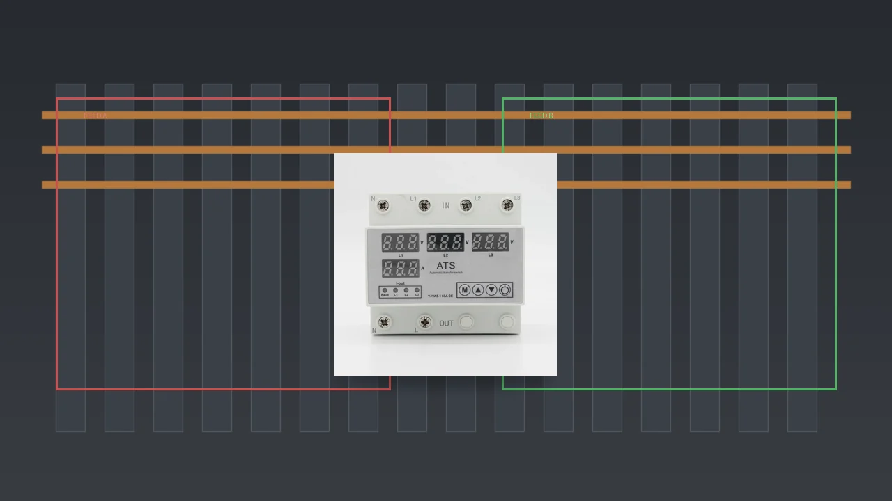
If the job is only to prove and label the order once, stop after the checklist and the tags. If the feed keeps presenting the wrong or unstable sequence and the load must stay on a healthy ordered output, you have left the meter’s job and entered a switching-device decision.
When a Yijin Conversion Switch Fits After the Test
Choose YJVA3-1 when the job needs automatic detect-and-switch — knowing Yijin does not sell the handheld meter.
Yijin’s live Transfer Switch category is titled Phase Sequence Converter on the site. It lists manual YJFT families and the automatic conversion switch.
It does not list a phase rotation meter or phase sequence indicator instrument. Say that plainly before any SKU talk: Yijin does not sell a phase rotation meter.
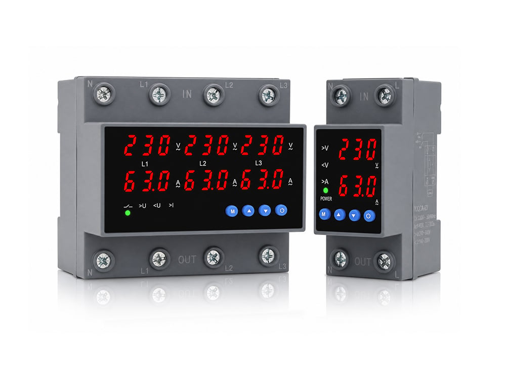
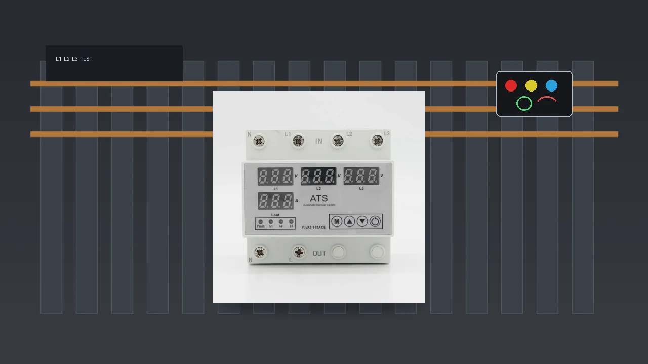
The model that matches an after-test “make the output healthy automatically” need is the YJVA3-1 automatic phase sequence conversion switch. Its page describes a 3P+N four-in-two-out module that monitors multiple inputs, and when there is a phase sequence fault it automatically detects and switches to the normal phase sequence power supply output. Overvoltage, undervoltage, and overcurrent functions sit in the same unit, and the output phase sequence is one of the values the user can set.
Printed values on the YJVA3-1 page include rated operational voltage AC230V, rated working current 3A~63A adjustable with a default of 63A, frequency 50Hz/60Hz, undervoltage cut-off 140V-200V adjustable with a default of 170V, overvoltage cut-off 240V-300V adjustable with a default of 270V, phase sequence switching detection time OFF-1s~500s adjustable with a default of 10 seconds, and a note that the maximum line voltage should not exceed 330VAC.
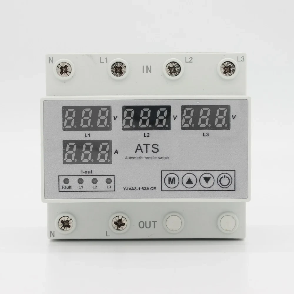
Scan the same printed values in the table below.
| Printed parameter (YJVA3-1 page) | Page value |
|---|---|
| Poles | 3P+N |
| Rated operational voltage | AC230V |
| Rated working current | 3A~63A adjustable (default 63A) |
| Frequency | 50Hz/60Hz |
| Undervoltage cut-off | 140V-200V adjustable (default 170V) |
| Overvoltage cut-off | 240V-300V adjustable (default 270V) |
| Phase sequence switching detection time | OFF-1s~500s adjustable (default 10 seconds) |
| Max line voltage note | should not exceed 330VAC |
| Mounting | Standard rail installation |
The page also states the product needs a companion miniature circuit breaker for short-circuit protection, that the neutral is a straight-through conductor without disconnection, and that the module itself is not an isolation device. Those limits stay with the printed text — no invented UL or IEC listing for this SKU.
The YJVA3-1 mounts on a DIN rail inside the cabinet. When you only need to hand-change sources and keep the verified labels visible, the manual YJFT-125 4P page’s label window for clear labeling of power sources is the closer neighbour in the same category. It is not a substitute for a handheld meter either.
For naming disputes on drawings before you ever clip on, see ABC and ACB phase sequence. For detector versus indicator versus relay classes, use the detector-circuit companion linked above. Questions about printed parameters or fit against a board layout can go to contact us as a normal follow-up, not as a quote workflow.
FAQ
How do I test phase sequence with a handheld meter?
Land the three leads on the three line conductors, confirm all phase-presence indicators are on, then read clockwise versus reverse. Tag a PASS; de-energize and swap any two phases after a reverse FAIL, then retest.
What if one phase lamp stays off during the test?
Treat it as an open or missing phase at that clip. Do not trust the sequence indication until all three presence lamps are on and you have confirmed three live phases.
Does ABC vs ACB mean the panel is wired wrong?
No. ABC and ACB are two common letter names for the only two three-phase rotations. A reverse reading means the order at the clips is the opposite of the expected one — not that a third sequence exists.
Can I bump the motor instead of using a meter?
Sometimes, on loads that tolerate a brief reverse. When reverse rotation can damage the machine, use a phase rotation meter on the supply first instead of bumping.
Will a rotation meter fix a reversed feed by itself?
No. The meter only indicates. Correcting the feed still means rearranging conductors after lockout, or installing a switching device that can change the output order.
Does Yijin sell a phase rotation meter?
No. The live Transfer Switch category sells the YJVA3-1 conversion switch and the manual YJFT families. It does not sell a handheld phase sequence indicator.
When does the YJVA3-1 fit after a reverse or unstable sequence test?
When the load must keep running on a healthy ordered supply and the page-stated detect-and-switch behaviour matches the job. Open the product page for the printed parameter table before you order.
Can I trust a simple indicator on a VFD output?
Often not. Field reports say simple lamp-style indicators can misread on the load side of a drive. Prefer manufacturer guidance for that instrument, and do not treat a odd VFD-side reading as a catalogue fact about Yijin hardware.
References
- Phase sequence indicator requirements sample covering 61557-7 class instruments — What a Field Phase-Sequence Test Is Deciding
- Phase sequence verification: dead check vs live rotation — Prep Before You Clip On: Dead Trace vs Live Indication
- Phase sequence indicator types and lamp methods — Lamp Method: What Brightness Can and Cannot Prove
- Phase sequence indicator practical overview — Handheld Meter PASS/FAIL Checklist
- NJIT ECE lab notes on abc vs acb sequence — What a Field Phase-Sequence Test Is Deciding
- EEVblog forum: simple phase sequence detector caveats — What the Test Cannot Do: Indication Is Not Switching