 Yueqing Yijin Electronics Co., Ltd.




How to Read a Modular Contactor Wiring Diagram
A modular contactor wiring diagram is a contact map: it shows how the coil circuit and the power poles relate, and it stops before it invents wire size or branch protection. The sections below walk a US panel drawing the same way a field reader should — coil first, then 1P/2P/4P paths, then any printed NO/NC marks, then the blank edge of the sheet.
Landing steps and DIN-rail seating belong on the install sibling, not here. Browse the live contactor range while you compare marks.
When a Modular Contactor Drawing Shows Up in a Panel Package
A modular contactor wiring diagram is a contact map for remote switching in a panel or control package, not a full job ticket.
Estimators and electricians usually meet it as a small block on a lighting, HVAC-control, or distribution drawing for a modular AC contactor that will sit on a DIN rail.
The sheet’s job is narrow. It shows which terminals belong to the control circuit and which belong to the load paths.
It does not replace the nameplate on the device in your hand. It also does not replace the branch protective device upstream of that device.
In US work the drawing still matters even when the product page uses IEC or GB language. Read the marks as marks. Page labels are not UL Listed or NEC approval language.
After you finish the read, seating and landing steps live on How to Install an AC Contactor. Pole buying lives on AC Contactor 1 Pole vs 2 Pole.
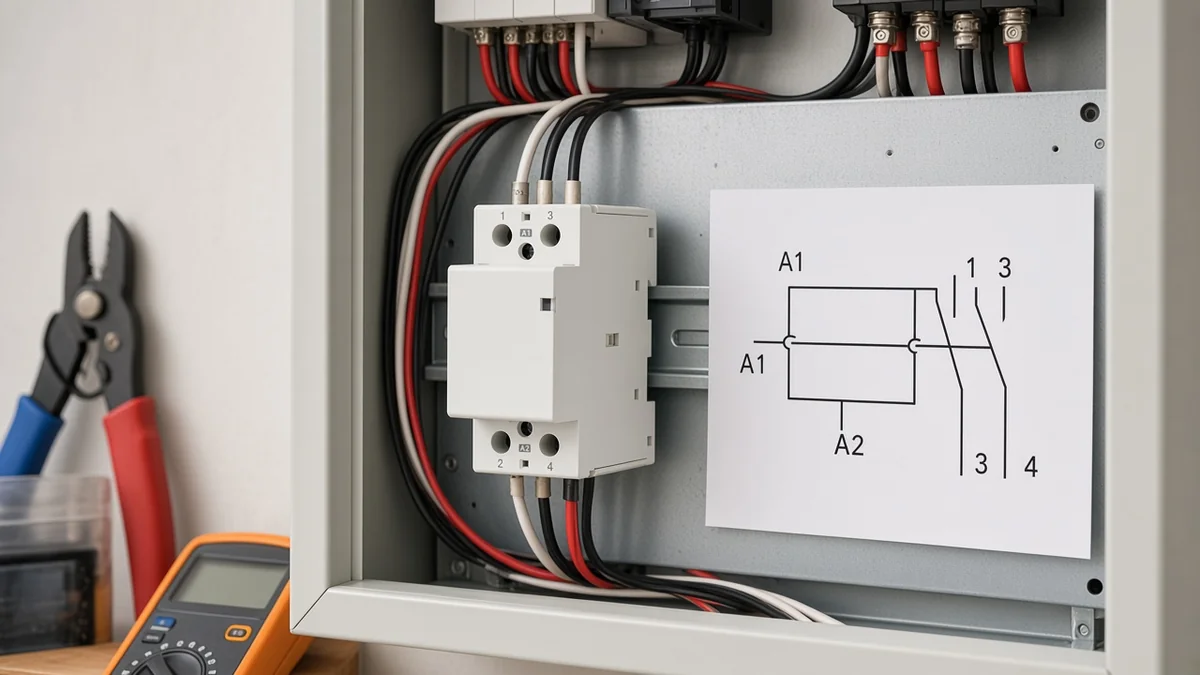
Find the Coil Circuit First (A1 and A2)
A1 and A2 are the coil terminals. They are not the power poles.
On almost every contactor wiring diagram, those two marks identify the control circuit that energizes the electromagnet. In product language those marks are the coil terminals A1/A2.
When the control supply lands across A1 and A2 at the rated coil voltage, the main contacts change state. On a conventional normally open frame, that means the power poles close. When the coil drops out, the contacts return.
Do not size the coil from the load voltage on the same sheet. A lighting bank may sit on higher-voltage poles while the coil is a different control voltage printed on the device. The diagram only works when the coil mark and the control supply match.
From the field: Forum readers on Electrician Talk often treat A2 as “always neutral.” On many AC coils polarity is not the physics problem — convention is A1 hot and A2 return — but the drawing and the coil rating still win. If the sheet shows a phase-to-phase coil or a marked DC polarity, follow the sheet, not the habit.

Keep thin control conductors on A1/A2 and thicker load conductors on the numbered poles. Confusing those two groups is the fastest way to misread the map before a single screw is tightened.
Buyers who ask about an A1 A2 contactor connection are usually asking about this coil pair.
Map 1P, 2P, and 4P Power Contacts on the Sheet
Pole count names how many power paths switch together; the coil is still two terminals.
A 1P / 2P / 4P title on the sheet is about power poles, not about how many coil screws exist.
A 1P map shows one switched pair. A 2P map shows two pairs that move together. A 4P map shows four.
Modular sheets usually number those pairs instead of using only HVAC-style L1/T1 letters. Common modular numbering looks like this:
| Pole count on the sheet | Typical power pairs | What the coil still looks like |
|---|---|---|
| 1P | 1–2 | A1 / A2 |
| 2P | 1–2 and 3–4 | A1 / A2 |
| 4P | 1–2, 3–4, 5–6, 7–8 | A1 / A2 |
On many 2P faces you will see 1 and 3 on the line side with 2 and 4 on the load side. That is two switched paths, not two coils.
Field threads on a two-pole normally-open modular frame spell the same map: A1/A2 for the coil, then 1–2 or 3–4 as one usable pole if only one path is needed.
Industrial motor sketches often print L1/L2/L3 and T1/T2/T3. That is another marking family.
When your panel package uses modular numbers, read the numbers. An outdoor HVAC definite-purpose sketch is a different map.
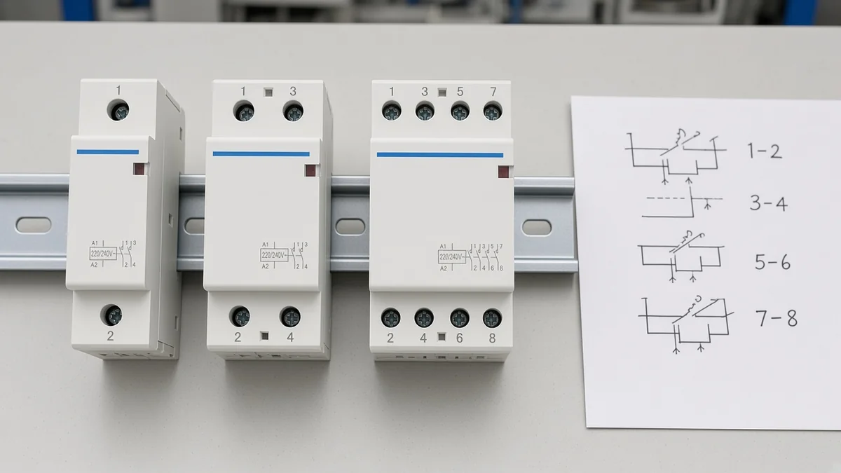
If the sheet title says 2P but only one pair is drawn, trust the drawn paths. Titles summarize; the contact map decides.
Read NO and NC Only When the Sheet Prints Them
NO and NC describe contact state with the coil de-energized; auxiliaries are not the coil.
On a printed sheet the NO / NC letters are state labels, not a second set of coil screws. Normally open means the path is open until the coil pulls in. Normally closed means the path is closed until the coil pulls in.
Read those letters only where the sheet actually prints them. Many modular household frames ship as conventional normally open power poles.
Some catalogues show mixed NO/NC power arrangements. If your drawing is silent, leave the contact state alone instead of inventing an NC power pole from memory.
Auxiliary marks such as 13/14 (often NO) and 21/22 (often NC) are status or interlock contacts when they appear. They are not A1 and A2.
Field threads warn about landing coil voltage on 13/14 and treating that pair as the magnet — that is a different mistake from misreading a power pole.
Yijin’s live product pages state that conventional products are normally open and that normally closed products can be customized. Use that page note when you compare hardware, not as a free rewrite of a silent diagram.
Stop Where the Diagram Stops
The sheet does not size the wire or pick the branch protective device.
A wiring diagram shows relative terminal arrangement. It is not an ampacity table, a torque chart, or a short-circuit study.
A contactor switches. It does not replace the breaker or fuse that clears a fault.
Independent technical pages make the same boundary: the contactor is not short-circuit protection. If your drawing omits the upstream device, the omission is real.
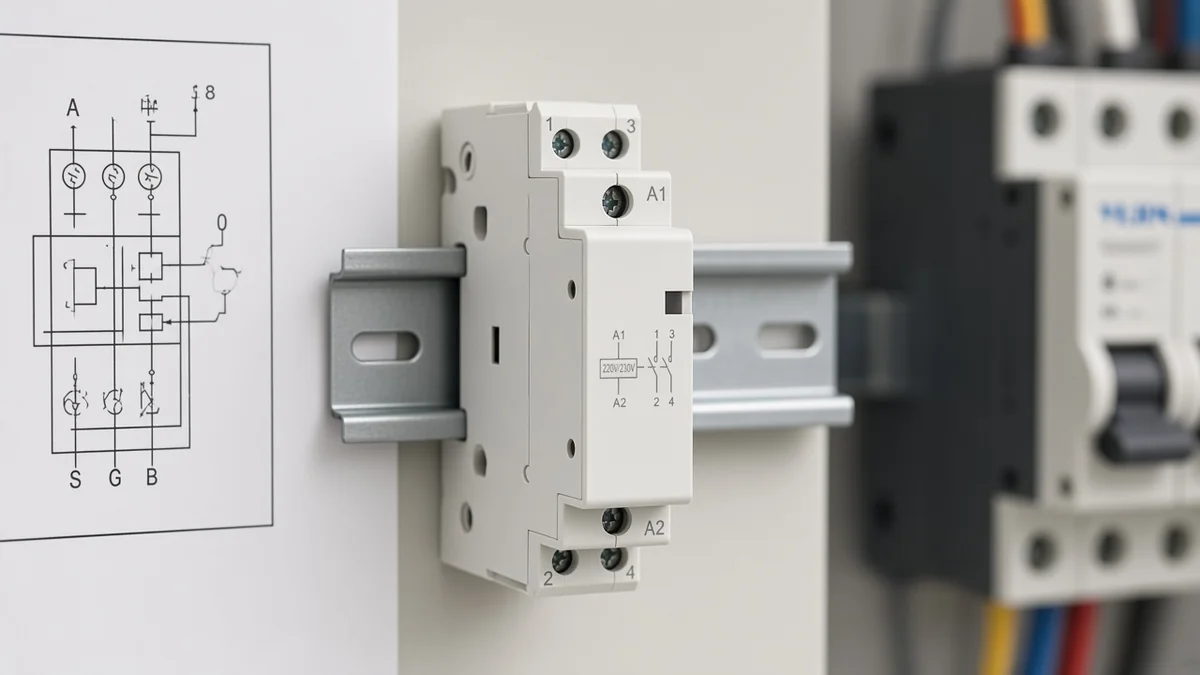
Also stop before importing install seating into the read. The retainer clip, rail immersion, and live-load landing checks belong on the install article. Here the useful end of the instruction is the last printed mark.
| Mark or block on the sheet | What it can tell you | What it cannot invent |
|---|---|---|
| A1 / A2 | Which screws are the coil | Wire size of the control circuit |
| 1–2 / 3–4 / 5–6 / 7–8 | Which power paths switch | Branch breaker rating |
| NO / NC | Contact state when the coil is off | Whether an unprinted aux exists |
| Coil voltage print | Required control supply class | UL or NEC approval |
| Blank margin | End of the drawing | Missing protection or torque |
Choose a Yijin Modular Contactor for the Marks You Just Read
Compare a 2P modular diagram to the YJC1-63 2P modular AC contactor when the sheet shows two power pairs plus A1/A2.
The live nameplate photo on that page shows the two pole pairs, the coil screws, a 220V/230V coil mark, and an Ie 63A class mark.
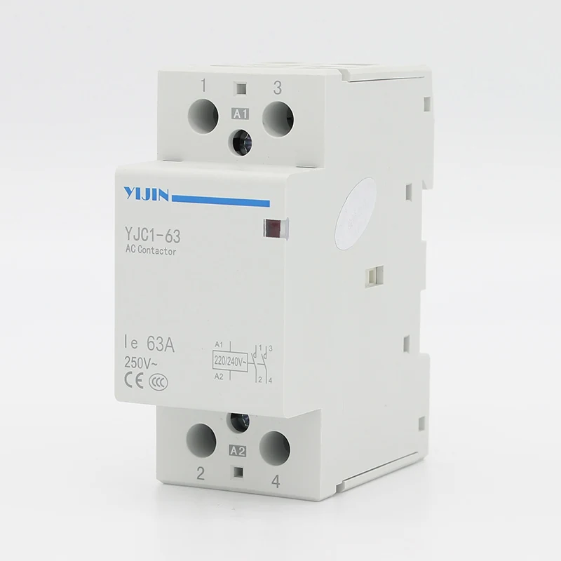
That product photo is the frame to hold next to a 2P contact map.
The same family covers the contact maps above.
| Live Yijin frame | Pole map on the page | When it matches the sheet |
|---|---|---|
| YJC1-63 1P | One power pair + A1/A2 | Single switched path |
| YJC1-63 2P | Two pairs + A1/A2 | Most common 2P modular diagram |
| YJC1-63 4P | Four pairs (1/3/5/7 over 2/4/6/8) + coil | Four switched paths |
| YJC-1-25 2P | Two pairs + A1/A2, Ie 25A class | 2P map with 25A class mark |
| YJC-1-25 4P | Four pairs, Ie 25A class | 4P map with 25A class mark |
All five sit on the contactor hub as a DIN-rail modular frame family.
Shared page language names AC 50Hz (or 60Hz) at 230V working voltage, AC-7a use category, TH35-7.5 rail, and GB17885 / IEC1095 statements.
Those are page labels for a US English buyer audience. They are not UL Listed or NEC approval claims. Branch protection still sits outside every one of those product pages.
Choose YJC1-63 when you need the 1P option or the 63A class map. Choose YJC-1-25 when the printed current class is 25A and the sheet is 2P or 4P.
Leave both when the symbol is an outdoor HVAC definite-purpose contactor rather than a modular DIN-rail frame.
FAQ
What are A1 and A2 on a modular contactor wiring diagram?
They are the coil terminals. Apply the rated control supply across them to operate the electromagnet. They are not the numbered power poles that carry the load.
Is A2 always the neutral on the coil?
No. Many AC drawings use A2 as the return, and that habit is common, but the control supply on your sheet decides. Phase-to-phase coils and marked DC polarity are real exceptions.
How do I read a 2-pole modular contactor diagram?
Find A1/A2 first. Then read two power pairs, often 1–2 and 3–4, as paths that switch together. If you only need one path, many field notes use either 1–2 or 3–4 — still not a second coil.
What do NO and NC mean on the drawing?
Normally open and normally closed describe the contact state with the coil de-energized. Read them only where printed. Auxiliary 13/14 or 21/22 marks are not the coil.
Does the wiring diagram tell me which breaker and wire size to use?
No. The diagram maps terminals. Branch protection and conductor sizing come from the electrical design, not from the contactor block alone.
Which Yijin modular contactor matches a 2P diagram with A1/A2?
Start with the YJC1-63 2P page and compare the printed two-pair map and coil mark. Move to YJC-1-25 2P when the current class on the sheet is the 25A map.
Can I use only one pole on a 2-pole modular contactor?
Field discussions say yes for a single switched path using one pair, while the unused pair stays unused. The coil is still A1/A2. Confirm the exact sheet before you treat that as the job design.
How is a modular numbered diagram different from an L1/T1 HVAC sketch?
Modular DIN-rail sheets usually number pole pairs. Outdoor definite-purpose HVAC sketches often use L and T letters. Same coil idea, different marking family — do not swap the maps blindly.