 Yueqing Yijin Electronics Co., Ltd.
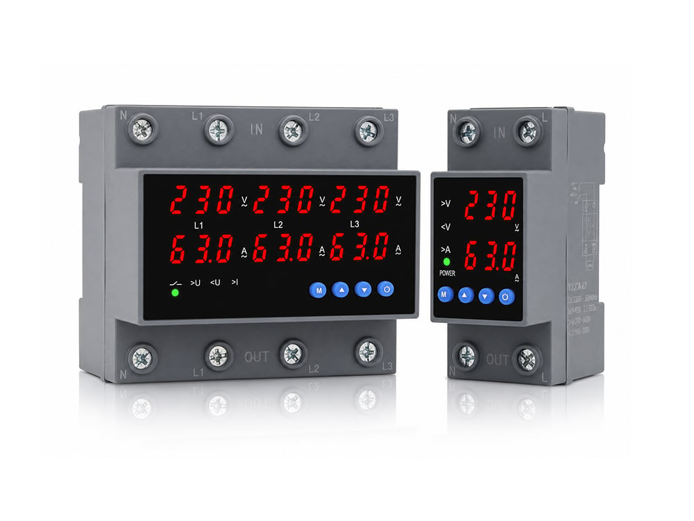



SPD Surge Protective Device 4P — Pole Fit for Three-Phase Boards
A spd surge protective device 4p is the four-pole configuration that covers L1, L2, L3, and N on a three-phase four-wire board — not a “safer” upgrade over every 3P unit. This article separates pole count from internal topology, maps earthing fit, shows how to read Uc/In/Imax/Up on a Class II four-module set, and points to a live Yijin 4P starting SKU.
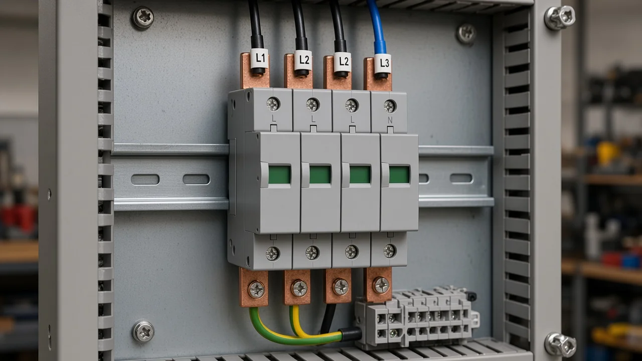
What a 4-Pole SPD Actually Protects (L1/L2/L3/N)
A 4P SPD is built to cover three phases plus neutral on a four-wire board — not four random modules. Encyclopedia wording treats a surge protective device (SPD) as equipment that limits very short voltage spikes on AC circuits, including nearby lightning and switching-style transients.
On a distribution board, those spikes can stress L1, L2, L3, N, and PE paths together. A plug-in strip on one receptacle does not do the same job as a hardwired multi-pole SPD on the rail.
Live Yijin Surge Protection Device pages list 1P/2P/3P/4P options on the same Class II family. Ordering a 4 pole surge protective device — the 4-pole / 4P SPD catalog option — means covering L1/L2/L3/N/PE paths on a DIN rail 35 mm mount instead of stopping at a 3-pole / 3P SPD when neutral is present.
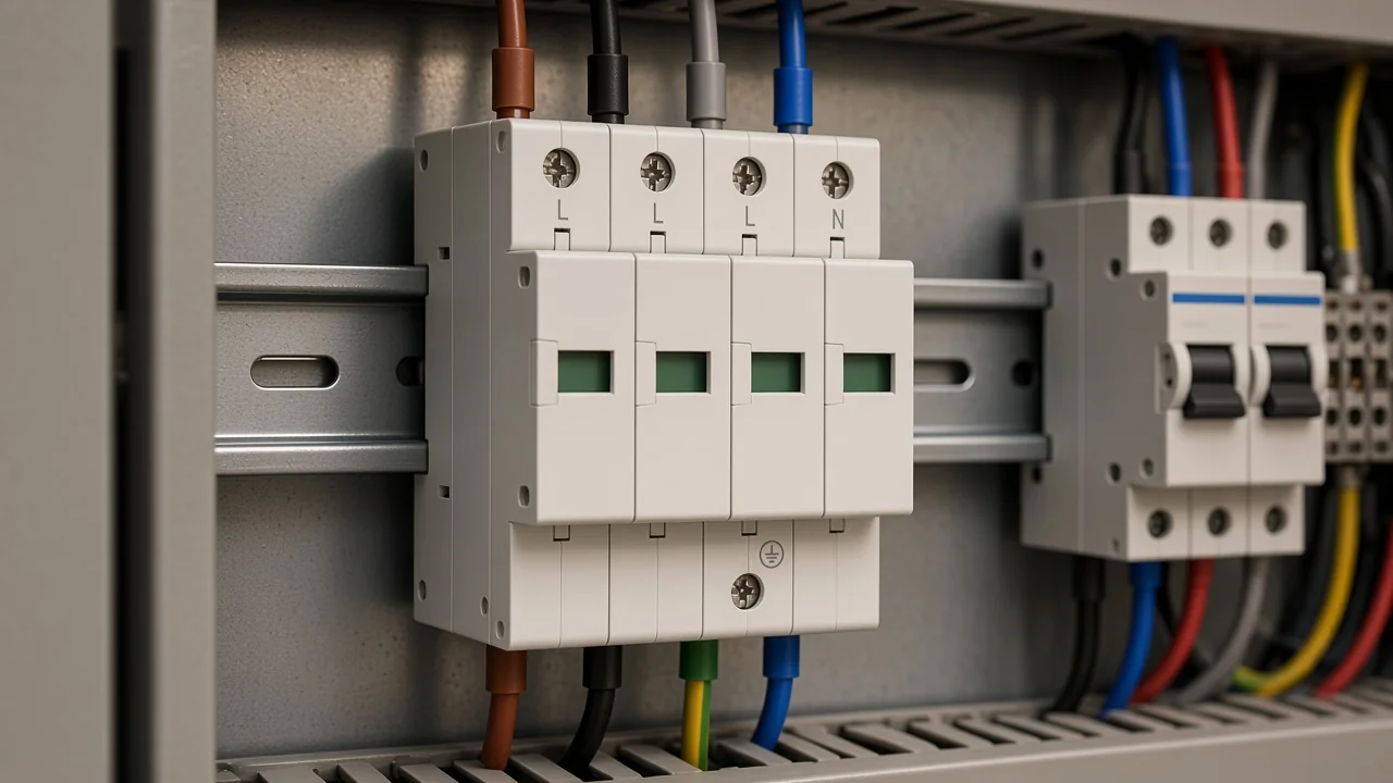
From the field: Electricians asking for whole-panel protection on a 120/208 board still get told “we only stock single-phase units” — source: Electrician Talk three-phase surge thread. That shopping gap is exactly why multi-pole / 4P language exists — single-phase cartridges do not automatically cover the other live legs.
For a broader three-phase family walk-through, see the sibling article on the 3 phase surge protection device. This page stays on the 4P fit decision.
4P vs 3P+N: Pole Count Is Not Topology
Treat 4P as terminal count; confirm whether the fourth path is 4+0 or 3+1 on the wiring diagram. Catalog language often says “4P” when four poles land on L1, L2, L3, and N. Industry guides also use “3P+N” for a 3+1 topology where three phase-to-neutral paths sit with a dedicated N-PE path.
A common 4+0 topology uses four similar voltage-limiting paths (often MOV-based) toward PE. A 3P+N / 3+1 topology usually keeps phase-to-neutral limiting paths and uses a different N-PE element such as a gas discharge tube (GDT) style path, so MOV / GDT choices on the fourth path matter.
Those two drawings are not interchangeable just because both show four modules. If the project specification calls for 3+1 and the datasheet only shows 4+0 (or the reverse), stop and match the circuit diagram before you buy.
Yijin product pages publish 1P–4P configuration options and Class II parameter tables. They do not replace a project wiring diagram for 4+0 versus 3+1 confirmation.
When 3P Beats 4P: Earthing and Neutral Presence
Choose 3P when there is no separate N (TN-C/PEN or three-wire); choose 4P when N and PE are separate and neutral must be protected. Earthing type is the fit driver — not the marketing hope that “more poles are always better.”
Independent application notes for AC SPD systems map the TN-S / TT / TN-C / TN-C-S / IT family to different pole starting points: TN-C toward 3P on PEN, TN-S and TT toward 4P (often 3+1 on TT), and IT / three-wire cases toward 3P. TN-C-S (PME-style) often needs 3P before the PEN split and 4P after N and PE separate.
| Earthing / wiring snapshot | Typical starting pole count | Why |
|---|---|---|
| TN-C / PEN present, no separate N | 3P | There is no separate neutral pole to protect |
| TN-S (separate N and PE) | 4P / evaluate 4+0 or 3+1 | Neutral is a live conductor that needs a path |
| TT (separate N and PE) | 4P, often 3+1 | N-PE path design matters for the system |
| TN-C-S after PEN split | Treat like TN-S → 4P class | N and PE are now separate |
| IT / three-wire without N | 3P | No neutral terminal to land |
Yijin series intros list suitability for TT, IT, TN-S, and N-C-S systems at AC 50 Hz (or 50–60 Hz on some SKUs), 380 V and below. That series scope still leaves the final 3P versus 4P choice to the board drawing.
A TN-S 4P SPD decision therefore starts with “is N separate?” — not with “does the catalog have a 4P SKU?”
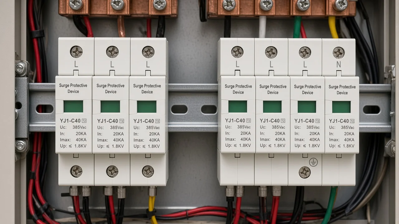
How to Read Uc, In, Imax, and Up on a 4P Module Set
Match Uc to continuous system voltage, then compare In/Imax capacity and Up to equipment needs using the Class II table. IEEE education material groups the Uc / In / Imax / Up set — continuous operating voltage (MCOV-class), nominal and maximum discharge current, and voltage protection level — as core SPD parameters.
On Yijin Class II (8/20 μs) pages, Uc (L-N) and Uc (N-PE) are the continuous voltages the table allows.
In is the nominal 8/20 μs discharge current. Imax is the maximum 8/20 μs discharge current. Up is the voltage protection level tied to that test wave.
Tip: Plants that put 480 V three-phase Delta onto arresters rated around 400 V nominal / 440 V clamp keep destroying the devices — source: Electrician Talk Delta arrester thread. Uc has to clear the continuous system voltage before In/Imax shopping starts.
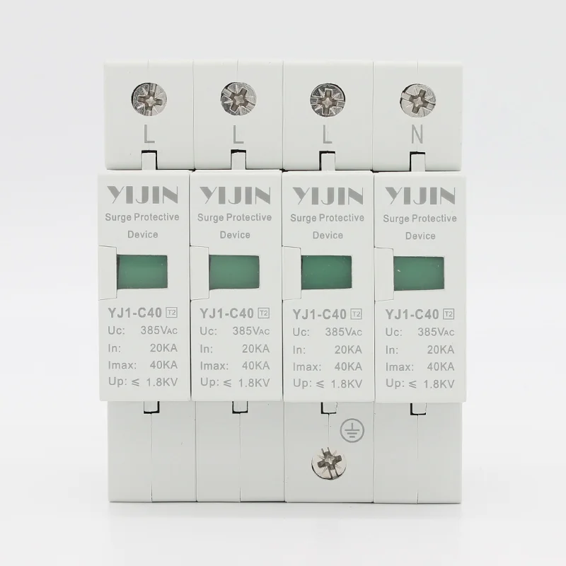
For the live YJ1-C40 table, Uc (L-N) is 385 V, Uc (N-PE) is 255 V, In (L-N) is 20 kA, Imax (L-N) is 40 kA, and Up is 1.8 kV. The page states Class II experiment language, a design basis of IEC61643-1 / GB18802.1, and a DIN rail 35 mm shell with a green-to-red failure window.
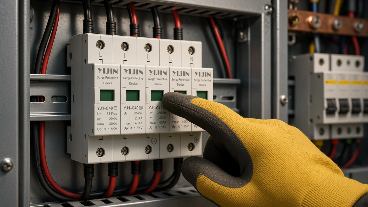
A lower Up is not automatically “better” if Uc no longer fits the system or if the topology is wrong. Read the four numbers together on the same 4P module set.
A Practical 4P SPD Selection Checklist
Confirm earthing, poles, topology diagram, then Uc/In/Imax/Up before you lock a SKU. Use the checklist as a scan order, not as a substitute for the project drawing.
- Confirm system voltage and whether the board is three-phase three-wire or four-wire.
- Name the earthing arrangement at the installation point (TN-S, TT, TN-C, TN-C-S, IT).
- Choose 3P or 4P from neutral presence — not from “more poles feel safer.”
- Open the datasheet diagram and confirm 4+0 versus 3+1 / 3P+N if the spec uses those words.
- Scan Uc (L-N) and Uc (N-PE) against continuous voltage.
- Compare In and Imax for the Class II role, then check Up against equipment withstand expectations.
- Confirm DIN-rail space, failure indication, and any remote-signaling need from the product page.
- Keep Type 1 / Type 2 / Type 3 language as UL 1449 location education unless a listing is actually on the nameplate you are buying.
Yijin pages in this family print Class II experiment tables and an IEC61643-1 design basis. They do not print a verified UL Listed SPD claim in the site-facts package.
Recommended 4P Starting Point: YJ1-C40 and Capacity Siblings
Start with YJ1-C40 in 4P for a mid Class II board; step through the YJ1-B60 / D20 / YJ-B80 siblings using the published tables. The live YJ1-C40 surge protector lists 1P/2P/3P/4P options for TT/IT/TN-S/N-C-S systems at AC 50 Hz, 380 V and below.
YJ1-C40 publishes Uc (L-N) 385 V, Uc (N-PE) 255 V, In 20 kA, Imax 40 kA, and Up 1.8 kV on its Class II table, with response time stated as less than 25 nanoseconds and optional remote signaling.
| Model | Poles on page | In (kA) | Imax (kA) | Up (kV) | When it is the better 4P pick |
|---|---|---|---|---|---|
| YJ1-C40 | 1P/2P/3P/4P | 20 | 40 | 1.8 | Default mid Class II 4P start |
| YJ1-B60 | 1P/2P/3P/4P | 30 | 60 | 2.0 | Higher published table Imax |
| YJ1-D20 | 1P/2P/3P/4P | 10 | 20 | 1.5 | Lower In/Imax and lower Up |
| YJ-B80 | 1P/2P/3P/4P | 40 | 80 | 2.4 | Highest table Imax in this set |
Prefer the parameter table when marketing copy and the table disagree. Housing text that mentions UL94 V-0 describes plastic flammability, not a UL Listed SPD certificate.
Common 4P Fit Mistakes (and What to Check Instead)
Do not force 4P onto PEN-only sections, and do not undersize Uc before you compare In figures.
Do not treat UL94 V-0 housing language as a UL Listed SPD certificate. Most wasted orders come from naming shortcuts rather than missing In numbers.
Forcing a 4P device into a TN-C / PEN-only section invents a neutral terminal the system does not have. Swapping a 4P 4+0 module set for a specified 3P+N / 3+1 design without reading the diagram is the same class of error.
Undersizing continuous voltage relative to the real system — the Electrician Talk 480 V Delta failure pattern — will burn modules even when In looks large on paper. Shopping only single-phase cartridges for a 120/208 three-phase panel leaves uncovered live paths.
UL 1449 Type 1/2/3 language is useful location education. It is not a sticker already proven on every DIN-rail Class II page in this package, and site-facts v1.1 records no verified NEC compliance claim for Yijin SPDs.
FAQ
What does “4P” mean on an SPD?
It usually means four poles covering L1, L2, L3, and N on a three-phase four-wire board. Always confirm the datasheet terminals.
When should I choose 3P instead of 4P?
Choose 3P when there is no separate neutral at the installation point, such as TN-C / PEN or many three-wire arrangements. Choose 4P when N and PE are separate and neutral must be protected.
Is a 4P SPD the same as a 3P+N SPD?
Not always. 4P is terminal count; 3P+N often implies a 3+1 topology with a dedicated N-PE path. Match the wiring diagram.
How do I read Uc on a 4P module?
Uc is the maximum continuous operating voltage on the table. For YJ1-C40, Uc (L-N) is 385 V and Uc (N-PE) is 255 V — both must fit the continuous system.
What do In and Imax tell me?
On these Class II pages, In is the nominal 8/20 μs discharge current and Imax is the maximum 8/20 μs discharge current. Compare siblings after Uc fits.
Does a lower Up always mean a better 4P SPD?
No. Up is the residual voltage associated with the test wave. A lower Up that breaks Uc fit or uses the wrong topology is still a bad buy.
Are Yijin 4P SPDs UL Listed?
The reviewed pages state Class II tables, an IEC61643-1 design basis, and housing UL94 V-0 material language. This package does not establish a UL Listed SPD or NEC compliance claim.
Can single-phase SPDs replace a 4P unit on a 120/208 panel?
Not as a topology shortcut. Whole-panel three-phase coverage needs the live paths — and usually neutral — matched to the board, which is why buyers ask for true multi-pole / 4P devices.