 Yueqing Yijin Electronics Co., Ltd.




How Phase Sequence and Phase Rotation Split in the Field
Phase sequence is the order in which the line voltages reach their peaks, and phase rotation is the name crews also use when they mean the sweep of the field or the turn of the shaft. phase sequence vs phase rotation is that split, read as words first and as two different checks second.
A pump that runs backward and a generator sheet stamped clockwise are the usual ways the mix-up shows up. One asks which way the shaft is turning, and the other asks which line crests first before anyone ties two sources.
The pages that follow keep those checks apart, then name the live Yijin device that can change the output order when the fault is in the sequence. A lamp, a shaft view, and a conversion switch are three different tools.
What the two words name on a live three-phase job
Phase sequence is the peak order, and textbook English often uses phase rotation for that same order. On a motor job the second word slides over to the rotary field and then to the shaft, which is why the phrase phase sequence and phase rotation keeps showing up as if it were one thing.
Two orders exist on a three-phase supply. One family is A-B-C, and the other is A-C-B. Cycling the letters, as in B-C-A, stays inside the first family.
Balanced teaching sets place those crests 120 electrical degrees apart. A drawing of a 60 Hz system is described as returning to the same picture in 16.6 ms.
IEEE 100 is cited for the dictionary word phase sequence, while job talk keeps phase rotation anyway. Treat the dictionary as the peak-order word, and treat the extra meaning as something you have to pin down on site.
Resistive heaters do not care which family they see. The voltage on each line is still the voltage on each line.
| Job question | Word that belongs | What you actually watch |
|---|---|---|
| Which line crests first | phase sequence | The time order of the three voltages |
| Which way the field sweeps | phase rotation, in meter speech | A rotary-field lamp or a spinning disc |
| Which way the pump shaft turns | direction of rotation | The shaft end, or a controlled bump |
| Whether two sources may be tied | in phase, beyond the order | Voltage between the matching lines |
Which check a rotary-field lamp can finish
A rotary-field lamp, or a phase rotation indicator with a disc, reports the supply order. It does not tell you which way the shaft is turning.
The disc on a rotating indicator is driven like a tiny induction motor, so its spin follows the leads you clipped. Move the clips and the disc can reverse while the motor in the other room has not moved.
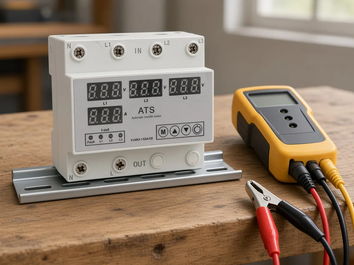
That bench pairing is the right mental picture: the device and the tester answer different questions. Clip the tester on the incoming lines if the question is peak order.
The Fluke 9040 manual describes a handheld indicator whose lamps show clockwise or counter-clockwise rotary field. The live Yijin switch is a different object, and those instrument ratings are not its ratings.
Rotary-field indication on that manual runs from 40 to 690 V ac. The frequency window printed beside it is 15 to 400 Hz.
The manual lists CAT III 600 V to ground for that check. It also lists CAT IV 300 V to ground.
Safety language on the manual cites IEC 61010. The phase-sequence test clause cited beside it is IEC 61557-7.
One warning in that manual is easy to miss: the rotary lamps can still light if the neutral is landed where a phase lead should be. A lit lamp with a neutral on the clip is not a clean reading of the three hot lines.
Crews sometimes ask a phase rotation monitor to do this lamp job and then expect a trip as well. A monitor that only alarms is still an indicator with a contact, not a device that rebuilds the output order.
What a two-lead swap does to the field
Swapping any two of the three hot leads reverses the rotary field in the stator. The rotor follows that field, so the shaft reverses with it.
Cycling all three leads, A to B, B to C, and C to A, keeps the same family. The motor does not see a new direction from a rotation of the labels alone.
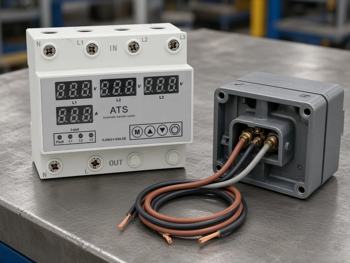
Leave the leads loose until the order you want is written down. Landing them “to see what happens” is how a fan ends up pushing air the wrong way through a damper that only works in one direction.
Do the swap on the load side of the starter when only that motor should reverse. Swapping the same pair on the feeder reverses every motor on that feeder.
A reversing starter automates the pair swap with a second contactor. The forward contactor is straight through, and the reverse contactor crosses two poles.
Why a clockwise stamp can fight the letters
A clockwise stamp is a viewing convention, not a second alphabet for A-B-C. One page will call an R-Y-B order clockwise, and a generator sheet can call A-B-C clockwise while a utility note calls A-B-C the other way.
From the field: The opening post on the Mike Holt sequence thread asks whether A-B-C marked counter-clockwise is the same thing as A-C-B marked clockwise, with a utility and a set of generators about to be paralleled.
Read the letters first. Then ask which end of the machine the clockwise note is looking from.
Phasor drawings used in teaching spin the vectors counter-clockwise. A meter face that paints clockwise as the “good” lamp is following motor habit, not that drawing.
If two notes disagree, interchange exactly two leads between the sources before a tie, and only after the letters are mapped. Guessing from the stamp alone is how the wrong pair gets crossed.
Letter identity for the lines themselves is a neighboring question, handled in the ABC and ACB phase sequence note. This page stays with the check split.
What a wrong order does to pumps, fans, and ties
Pumps and fans do not do their job in reverse. A cooling fan that pulls instead of pushes, or a pump that runs backward against a check valve, is the ordinary cost of a reversed field.
Heaters, lamps, and other loads without a shaft keep working. Saving the sequence check for “motors only” is fair only when nothing on the panel has a direction.
Two sources that can be connected at the same time need the same peak order and they also need to be in phase. Same order with a large angle between them still drives current across the tie.
A direct connection between two different phases is a short circuit. That is the failure mode behind the paralleling arguments, and it is larger than a pump that merely spins the wrong way.
Matching rotation on a lamp is not the whole tie check. Voltage between the phase you are calling A on the first source and A on the second source should sit near zero when the sources are truly in phase, and the same for B and for C.
The procedure for proving the order with instruments lives in how to test phase sequence. Use that when the task is the test itself.
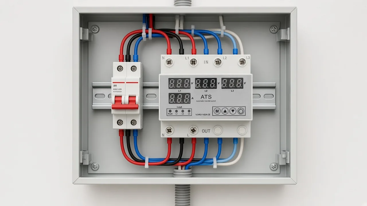
An enclosure like that still needs a human decision about order before the door closes. The breaker beside the device is there for fault current, which is a separate job from sequence.
Where the YJVA3-1 Fits After a Sequence Fault
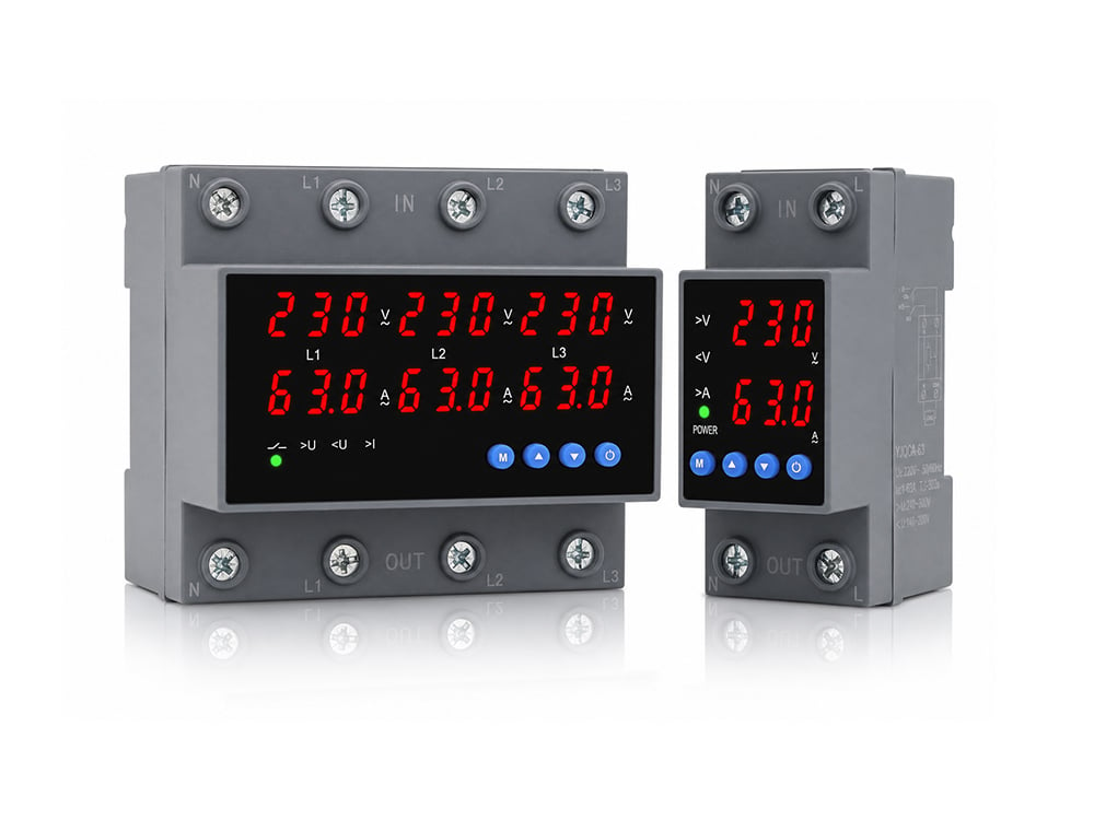
YJVA3-1 is the live 3P+N four-in-two-out automatic phase-sequence conversion switch, and it is the device that acts when the fault is the output order. A phase rotation indicator only reports the order it sees.
The phase-sequence converter shelf is where this switch sits on the site. That shelf is the phase-sequence category, and buyers who arrive there looking for a classic source-transfer contactor are in the wrong aisle.
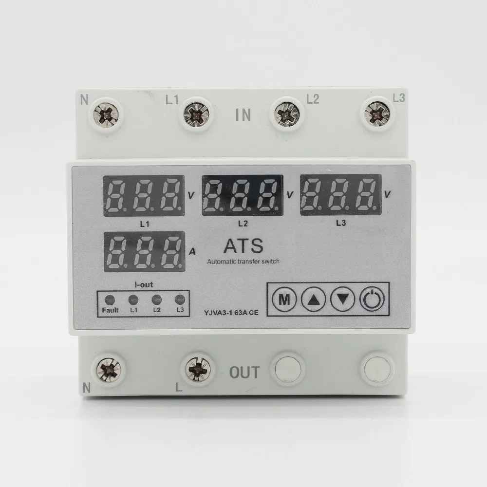
The face you can order is the YJVA3-1 four-in-two-out phase-sequence conversion switch. The user can set the overvoltage value, the undervoltage value, the overcurrent value, and the output phase sequence.
On a phase-sequence fault the page says the switch detects the fault and moves to the normal phase-sequence output after a delay the user sets. On an overvoltage, undervoltage, or overcurrent event it can open the output and bring it back after the delay that was set.
The four-in-two-out layout can watch more than one input and move to a backup input when one or two phases are outside the voltage window. That is a sequence-and-voltage action, not a shaft measurement.
Rated operational voltage on the live page is 230 V. Current can be set from 3 A to 63 A, and the printed default is 63 A.
Both 50 Hz and 60 Hz are printed for frequency. Undervoltage cutoff is adjustable from 140 V to 200 V, with a default of 170 V.
Set the high side from 240 V to 300 V for overvoltage cutoff, and keep 270 V as the default unless the load needs another point. Overcurrent cutoff is adjustable from 3 A to 63 A, with a default of 63 A.
Leave sequence detection off, or set it from 1 second to 500 seconds, and the printed default is 10 seconds. Power-on delay uses that same 1 second to 500 seconds span, again with a default of 10 seconds.
The combined power-on and power-off delay defaults to 30 seconds. Reset delay after an overcurrent trip also defaults to 30 seconds.
The page counts an overcurrent as confirmed only after 6 seconds. Line voltage should stay at or below 330 V.
| Window the user can set | Printed range | Default on the page |
|---|---|---|
| Operational voltage | 230 V | printed as the rated value |
| Working current | 3 A to 63 A | 63 A |
| Frequency | 50 Hz and 60 Hz | both are printed |
| Undervoltage cutoff | 140 V to 200 V | 170 V |
| Overvoltage cutoff | 240 V to 300 V | 270 V |
| Overcurrent cutoff | 3 A to 63 A | 63 A |
| Sequence detection time | off, or 1 second to 500 seconds | 10 seconds |
| Power-on delay | 1 second to 500 seconds | 10 seconds |
| On/off delay | 1 second to 500 seconds | 30 seconds |
| Overcurrent reset delay | 1 second to 500 seconds | 30 seconds |
| Overcurrent confirmation | 6 seconds | fixed on the page |
| Line voltage limit | 330 V | do not exceed |
Panel work in the United States sits inside the National Electrical Code for conductor identification and overcurrent protection. That market context is not a listing of YJVA3-1, and the live page does not print a UL listing or an IEC certificate number.
The neutral on this switch is a straight-through conductor and is not opened. The page also says the product has no isolation function, so the upstream breaker has to be open before anyone works on the load side.
Short-circuit current is outside what this switch clears. Pair it with an upstream miniature breaker, the way the page asks.
A phase rotation relay that only drops out a contactor is a different purchase. Buy YJVA3-1 when the output order itself has to change, and skip it when the only missing tool is a shaft reading.
Life on the page is stated as more than 100000 operations, on a standard rail. Nothing on the page states a negative-sequence current setpoint.
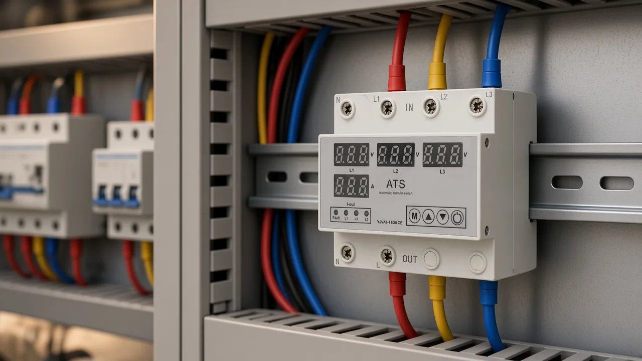
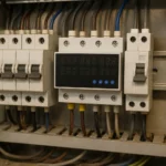
The cabinet scene is the installed look, with the incoming lines landed and the output leaving downward. It still does not replace a look at the shaft of whatever the output feeds.
What to confirm before the upstream breaker closes
Confirm three things in order, and stop if any one of them is still a guess. The order, the shaft, and the breaker ahead of the switch are the whole closeout.
Write the peak order you intend, in letters, and note which end of the motor the direction refers to. A clockwise word without that end is not yet an instruction.
Watch the shaft, or run a bump with the driven equipment safe to reverse for a moment. A lamp that already agreed with the letters does not retire that look.
Close the upstream breaker only after the output order and the trip windows match the load. The conversion switch can change sequence and can open on voltage or current; it is the wrong device to ask for a short-circuit interrupt.
FAQ
What is a phase sequence?
Phase sequence is the order in which the three line voltages reach their positive peaks. On a three-phase supply that order falls into two families, A-B-C or A-C-B.
What is a phase rotation?
Phase rotation is the field word for that same peak order, and it is also the word crews use for the rotary field or the shaft. Ask which of those meanings the note in front of you is using before you move a lead.
How do you know if phase rotation is correct?
Correct means the check matches the task. A rotary-field lamp is the right check for supply order, and a viewed shaft is the right check for the pump or the fan.
Is phase rotation always clockwise?
No. Clockwise depends on which end you are looking from, and on whether the note means the phasor drawing or the shaft.
How can a crew tell motor shaft direction from a meter lamp?
They cannot, not from the lamp alone. The lamp or disc follows the leads clipped on the supply, while the shaft follows the field inside that particular motor.
Does a sequence fault call for a rotation meter or a conversion switch?
A meter or a phase rotation indicator tells you the order. YJVA3-1 is the conversion switch that can change the output phase sequence when that order is the fault you need to clear.