 Yueqing Yijin Electronics Co., Ltd.




How to Check AC Contactor Coil Resistance and Pole Voltage
Here is how to check ac contactor coil resistance and contact voltage on a modular device: kill the power, lift the coil wires, read the winding path, then compare each closed pole with the printed working voltage.
The coil mark and the power-circuit voltage are different labels on the same faceplate.
The rest of this page walks the dead reading, the control-voltage window, and the two poles in that order.
What the coil check and the contact check each tell you
The coil check asks whether the winding is a continuous path, and the contact check asks whether each closed pole still shows the supply across it.
An AC contactor is a switch with two jobs that fail in different ways. The coil is the electromagnet. The main contact is the power pole that actually feeds the load.
A multimeter on ohms is asking a path question. A multimeter on AC volts is asking a pressure question. Mixing those settings is how a good winding gets condemned, or a burned pole gets a pass.
People who want how to check ac contactor with multimeter usually have both jobs in mind and only one meter. Do the path job while the circuit is dead. Do the voltage job only after the coil has been asked to pull in.
| Check | Meter setting | Circuit state | Reading that ends the debate |
|---|---|---|---|
| Coil path | Ohms | Supply off, coil wires lifted | Open path, or a bolted short where a winding should be |
| Control voltage | AC volts | Control circuit energized by a qualified person | Outside the printed pull-in window |
| Pole voltage | AC volts | Contactor pulled in | Working voltage still present from line screw to load screw |
A discolored coil housing is a reason to start the meter checks. The stain does not decide the part.
Prove the power is off before the resistance reading
Turn the supply off and prove the terminals are dead before the ohms leads touch the coil.
Resistance work belongs on a dead device. If the coil is still tied to a live control circuit, the meter is no longer looking at the winding alone, and the leads are in a panel that has not been made safe.
OSHA 1910.333 is the workplace rule behind that order. OSHA 1910.333 tells employers to de-energize live parts before work on or near them, and it treats parts under 50 V to ground as a separate case when burn and arc exposure do not rise.
The same section notes that some tests can only be performed with the circuit energized. The pole-voltage reading later on this page is that kind of test. The ohms reading is not.
Important: Lock the supply off before the resistance reading. CCOHS electrical safety guidance puts lockout ahead of maintenance and adjustments, and a live ohms measurement still waits on that lockout.
Prove the power terminals and the coil terminals are dead with the voltmeter before you turn the selector to ohms. Then lift the coil wires.
Read coil resistance with the coil wires lifted
Lift the coil wires, measure ohms, and compare the path with the voltage class marked on the coil.
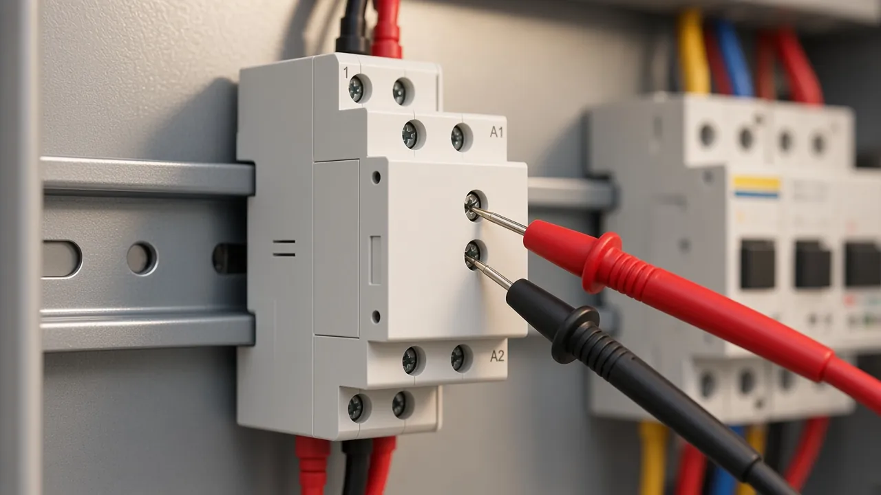
Testing ac contactor coil resistance starts at the coil terminals, not at the power screws. On this modular body those coil terminals are marked A1 and A2. The power screws are the pairs above and below them.
Leave the control wires on and the meter can read through the rest of the control circuit. An open winding can look fine, or a healthy winding can look open, depending on what else is still attached. Lift both coil conductors and separate the bare ends so they cannot touch the screws or each other.
Set the meter to ohms. Touch one lead to A1 and the other to A2.
You are looking for a continuous winding path, not for a number this product page never prints. The faceplate photo prints the coil as 220 V/230 V between A1 and A2.
That mark is the voltage class. An ohm limit is not printed beside it.
An open-line indication means the winding path is broken. A reading that behaves like a bolted short, the same way a piece of wire behaves, means the winding is not acting like a coil.
Anything in between needs the manufacturer’s coil data or a twin unit of the same coil class. The page does not supply that ohm figure, and none is added here.
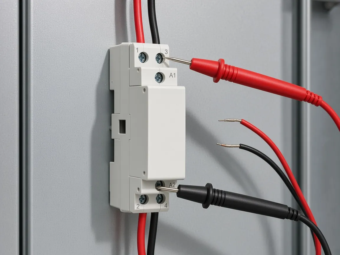
A continuity beeper is only a fast way to hear a closed path. Beeper thresholds differ by meter. Use the ohms display when you need to tell an open winding from a shorted one.
Compare control voltage with the printed pull-in window
The faceplate coil is marked 220 V/230 V, and the contactor should pull in between 80% and 110% of Us.
Us is the rated control supply voltage the percentages use. On this device the printed coil class is that 220 V/230 V mark. The page says the contactor can reliably close anywhere from 80% to 110% of Us, while release stays at or below 75% of Us and at or above 20% of Us.
That window is about the control voltage at A1 and A2 after the coil has warmed, not about the power poles. Put the meter on AC volts. With the control circuit calling, measure from A1 to A2.
If that voltage sits inside the pull-in window and the armature stays out, the coil or the magnet path is not completing the pull-in. If the voltage is below the window, the contactor has not been given the supply the faceplate asks for. Fix the control supply before you scrap the contactor.
Outdoor air-conditioner contactors in search results are often discussed as a low-voltage coil class. This modular faceplate is not that class. Read the mark in front of you.
A comment thread about a discolored air-conditioner coil made the same split: voltage present with no pull-in is a failed pull-in, and discoloration by itself was not treated as the verdict. The voltage number in that thread belonged to that air-conditioner part. Here the comparison is the printed window on Us.
Measure contact voltage on both poles
With the contactor in, measure each pole from its line terminal to its load terminal and compare that reading with the printed working voltage.
The faceplate shows two power paths. One path is terminal 1 to terminal 2. The other is terminal 3 to terminal 4.
Each path is a normally open contact on the conventional version of this model. Both have to be read. One healthy pole does not speak for the other.
This reading is live. It belongs with a person qualified for energized testing, because the information only exists while the contactor is pulled in and the supply is present.
Put the meter on AC volts. For the first pole, one lead goes on the line screw and the other on the matching load screw. Repeat on the second pole.
A closed pole that is passing the circuit shows only a small difference between those two screws. A closed pole that still presents the full working voltage from line to load is not passing the circuit. The load side is being left behind while the line side stays up.
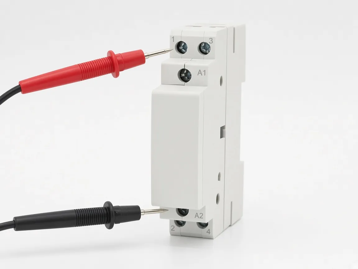
You can also press the armature with the power off and look for a continuous path across each pole. That dead check tells you whether the contacts touch.
It does not tell you how they behave once current and voltage are on them. Keep it as a prelude, then do the live pole reading if you are qualified to be in the energized panel.
Use the YJC-1-25 printed ratings as the bound
Use the faceplate’s printed coil class, current, working voltage, insulation voltage, and kilowatt lines, plus the Us percentages, and ignore any ohm number the page does not print.
The YJC-1-25 2P modular AC contactor is the DIN rail model these checks are bound to. The page title uses YJC-1-25. The faceplate on the product photo reads YJC1-25.
They are the same product page.
The same faceplate prints Ie (AC-7a) 25 A, Ue 230 V, Ui 500 V, AC-7a 5.4 kW, and AC-7b 1.5 kW.
Ue is the working voltage you compare with the pole reading. Ui is the insulation level. Leave it off the meter dial.
The kilowatt lines are the printed control-power figures for the two utilization categories. They describe the rating. They are not the pass/fail display on the meter.
| Faceplate line | Printed value | What the check uses it for |
|---|---|---|
| Coil between A1 and A2 | 220 V/230 V | Voltage class for the winding you just measured |
| Ie (AC-7a) | 25 A | Contact current rating of this model |
| Ue | 230 V | Working voltage a failed closed pole can still show |
| Ui | 500 V | Insulation rating only |
| AC-7a power | 5.4 kW | Printed category power |
| AC-7b power | 1.5 kW | Printed category power |
The HTML rating table on the same page also prints a 25-row working-current cell of 25/8.5 under a header that says the column is in volts, plus control power of 5.4/1.5 kW. When the faceplate and that cell disagree in layout, follow the faceplate lines above for the meter comparison and treat the HTML cell as a second printed string, not as a new test limit.
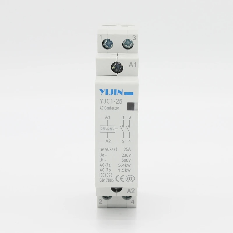
This bound fits a DIN-rail contactor in a residential buildings panel or any other contactor application that matches these ratings. It is a poor match if you need a different current row, a normally closed main contact as the standard build, or a coil class other than the 220 V/230 V mark.
Conventional units on the page are normally open. A normally closed build is described as a custom option. Check the contact state you actually have before you interpret an open path on a pole.
Stop metering when the reading already decides the part
An open coil, or Us inside the pull-in window with no pull-in, or full working voltage across a pole that should be closed, is enough to stop.
Three results end the procedure.
- The coil path is open, or it behaves like a bolted short, with the coil wires lifted and the supply proved dead.
- Control voltage at A1 and A2 sits inside the printed pull-in window and the armature does not pull in.
- The contactor is pulled in and a pole still shows the working voltage from its line screw to its load screw.
A discolored housing with a continuous winding and a clean pull-in falls outside those three results. Finish the pole reading before you decide.
If the control voltage never enters the window, the next work is the control supply, not another ohm reading on the same coil. If one pole is bad and the other is clean, the contactor is still bad. The load sees the weak pole.
From the field: Someone with a multimeter at home asked for test steps on a discolored coil and named the voltage class printed on that air-conditioner part. The useful replies did not treat the stain as the verdict. They asked whether the coil received its control voltage and whether it pulled in.
That is the same decision this modular check is built to make, using the marks on the YJC-1-25 faceplate instead of an air-conditioner coil class.
FAQ
Can the coil be measured with the control wires still attached?
No. The meter then sees the rest of the control circuit as well as the winding. Lift both coil conductors and keep the bare ends apart before you read ohms.
Is a modular contactor checked at 24 volts like an outdoor air conditioner contactor?
Only if its own coil mark says so. Search results often assume a low-voltage outdoor-unit coil.
The faceplate on this modular model prints a 220 V/230 V coil class. Use the mark on the device in your hand.
What does an open-line reading on the coil mean?
The winding path is open. With the coil wires lifted, an open-line ohms reading means the coil is not a continuous path and the contactor cannot pull in electrically.
Can the contacts be checked by pressing the armature with the power off?
Yes, as a dead continuity check across each pole. Pressing the armature shows whether the contacts touch. The live line-to-load voltage reading is the one that shows a pole failing under supply.
Is the printed 230 V figure the coil voltage?
Ue on the faceplate is the working voltage of the power circuit. The coil has its own box, printed as 220 V/230 V between A1 and A2.
They can share a number and still be different labels. Read the coil box for the coil, and read Ue for the poles.
Why is pull-in given as a percent of Us rather than one resistance number?
The page prints a pull-in and release window against Us, and it does not print coil ohms. The percentage window is the comparison the text actually gives you once the coil class is known from the faceplate.
Do both poles need a separate contact-voltage reading?
Yes. This is a 2-pole body, with one path from terminal 1 to terminal 2 and another from terminal 3 to terminal 4.
Read both. A clean pole does not clear its neighbor.
References
- Occupational Safety and Health Administration, 1910.333 — Selection and use of work practices. De-energize live parts before work on or near them, with a note for tests that can only be performed energized.
- Canadian Centre for Occupational Health and Safety, Electrical safety — basic information. Lock out the supply before maintenance or adjustments.