 Yueqing Yijin Electronics Co., Ltd.




What a Split AC Contactor Wiring Diagram Usually Shows
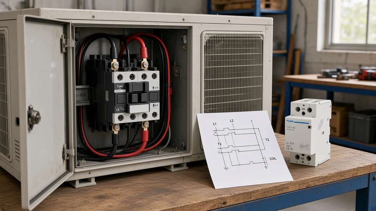
A split ac contactor wiring diagram usually shows the outdoor unit / condenser contactor on a split-system air conditioner: incoming line, switched load to the compressor and outdoor fan, and a separate coil path. It is not automatically the same document as a modular DIN-rail contactor map with numbered poles. This article names that mix-up, decodes the outdoor marks, contrasts the modular legend, and states an honest fit rule for Yijin’s live modular catalogue.
What “Split AC Contactor Wiring Diagram” Usually Means
It usually means an outdoor-section contactor map on a split-system condenser, not a DIN modular contact legend.
In US HVAC search language, “split AC” points to a split-system air conditioner. Related searches for an air conditioning ac contactor wiring diagram or split ac contactor wiring usually land on the same outdoor-unit sheet family. OEM outdoor sheets label the high-voltage switch as the contactor, show field supply on the line side, and route compressor and outdoor-fan conductors on the load side.
That document family lives inside the outdoor control box. It is written for a definite-purpose outdoor contactor, not for a household DIN-rail modular frame.
Typical outdoor titles say “Split System Air Conditioner (Outdoor Section)” or similar. The legend often marks field wiring versus factory wiring, and it may show a dual capacitor, pressure switches, or an anti-short-cycle timer around the contactor — still the same outdoor map family.
If you arrived here holding a modular panel drawing with A1/A2 and numbered poles 1-2 / 3-4, you are already in a different map. Read the sibling on modular contactor wiring diagrams for that literacy path.
Decode Line and Load Marks on the Outdoor Sheet
L terminals are incoming line; T terminals are switched load.
On a typical single-phase outdoor sheet, L1 and L2 mark the supply side of the contactor. T1 and T2 mark the equipment side that feeds the compressor and outdoor fan once the contacts close.
Matching pairs stay together: L1 with T1, L2 with T2. Treat L1 L2 / T1 T2 as one mark family for line versus load, not as coil screws.
| Mark group | Usually means | Does not mean by itself |
|---|---|---|
| L1 / L2 | Incoming line / supply | Coil terminals |
| T1 / T2 | Switched load toward compressor / fan | Branch-breaker size |
| Coil / CC | Control electromagnet path | High-voltage line |
Screws often look identical in a photo. Molded marks and the OEM sheet still win over color habits and top-versus-bottom guesses.
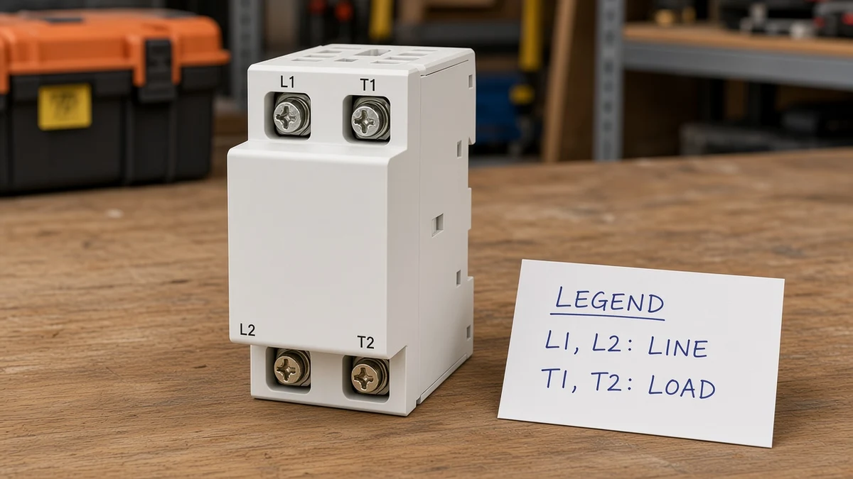
From the field: HVAC techs describe the outdoor job the same way — high-voltage L1/L2 become T1/T2 when the low-voltage coil pulls in, and “the control voltage is completely separate from the line/load voltage.” (Source: https://www.reddit.com/r/HVAC/comments/6hptfa/contactor_wiring/).
Separate the Coil Path from the High-Voltage Legs
Keep the coil path off the high-voltage legs on the outdoor sheet.
Residential outdoor sheets often print 24 V on that control path when the drawing says so.
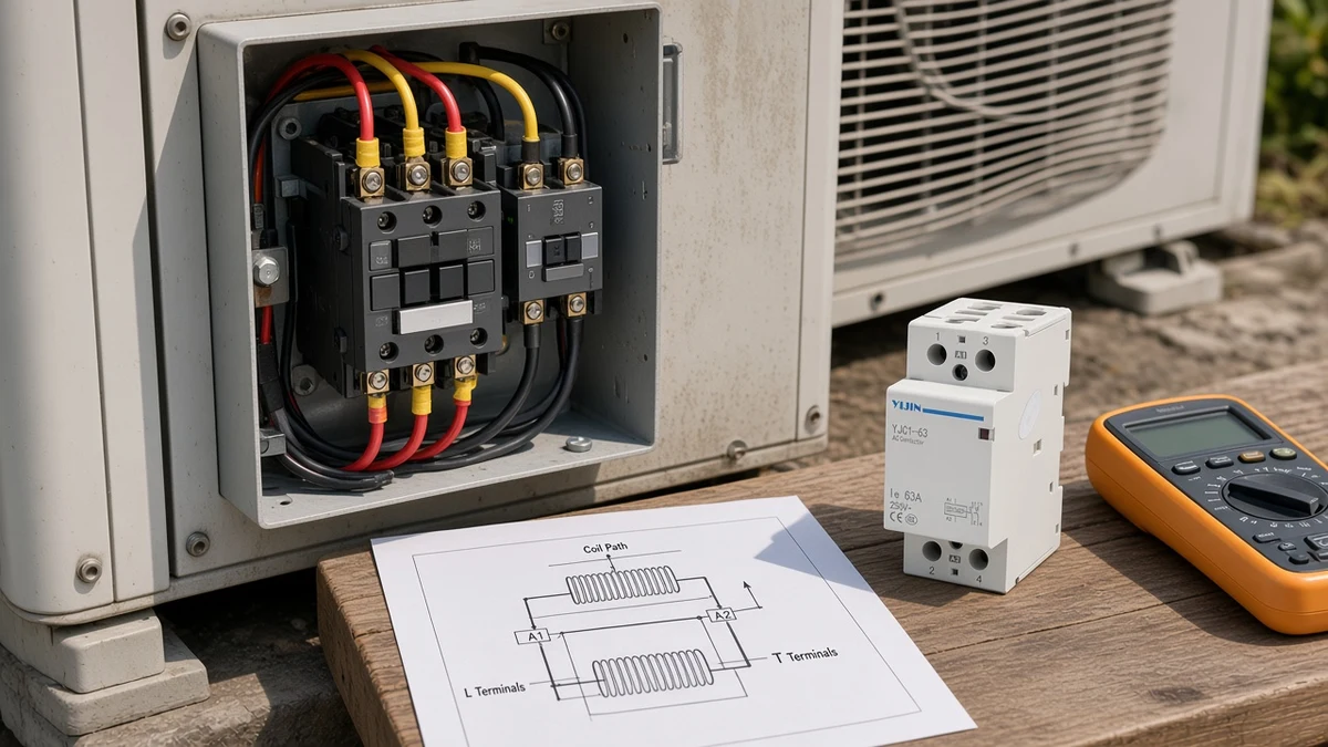
Outdoor diagrams commonly show a contactor coil (24 V typical) fed from the indoor control circuit and labeled CC on many sheets. Many residential sheets note a 24 VAC class-2 field connection and route the cooling call through Y and common, often with outdoor safeties in series. That is OEM-sheet language, not a universal law for every brand and tonnage.
Do not land the 208/230 V legs on the coil screws. Do not treat the coil terminals as another L/T pair. Energizing the coil closes the main contacts; removing coil voltage opens them on a conventional normally-open outdoor contactor.
If the printed coil rating is missing from the device in front of you, stop and read the OEM diagram and the replacement nameplate before assuming 24 V.
Definite-Purpose Outdoor Maps Are Not Modular DIN Maps
DP outdoor L/T maps and modular numbered A1/A2 maps are different document families.
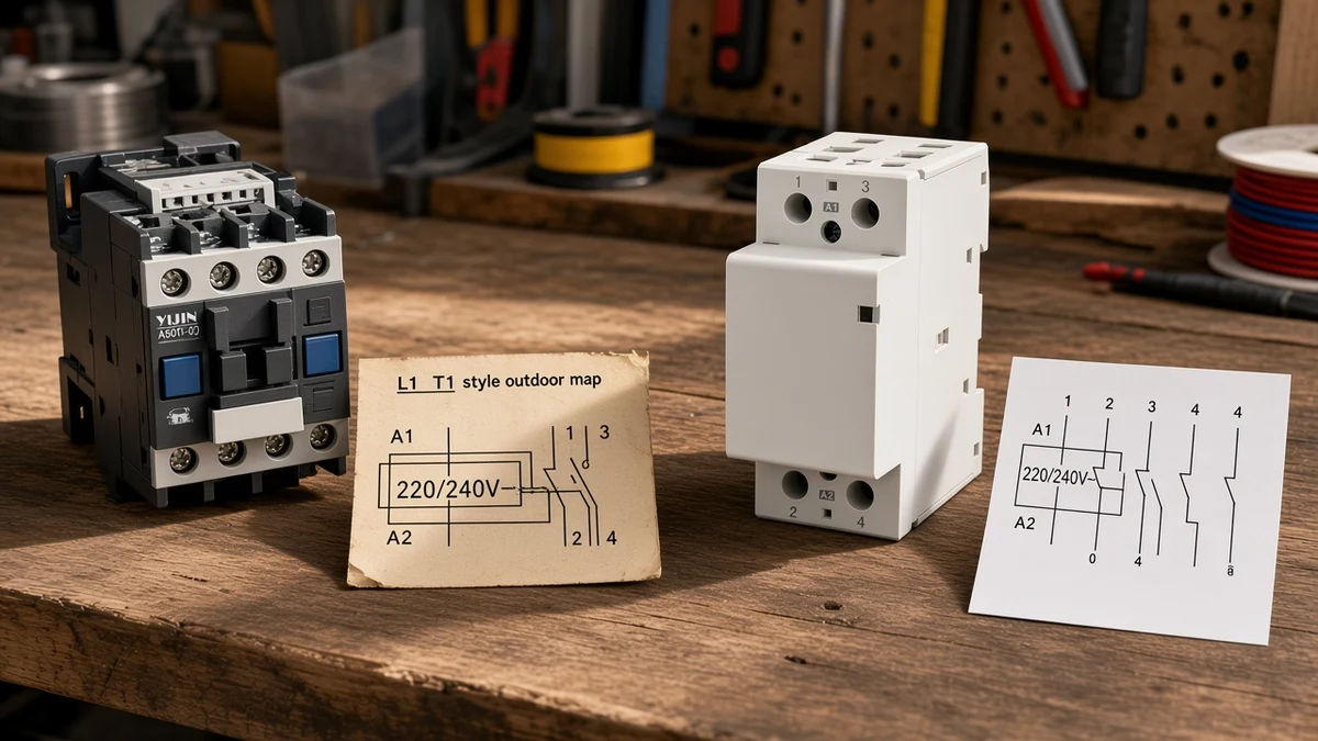
HVAC outdoor contactors are commonly a definite purpose contactor class aimed at compressor and condenser switching. Their sheets speak in L1/T1 language, outdoor-fan and capacitor paths, and low-voltage control notes. Modular DIN-rail AC contactors speak a different legend: A1/A2 for the coil and numbered power poles such as 1-2 and 3-4.
| Document family | Common power marks | Common coil marks | Typical home |
|---|---|---|---|
| Outdoor DP / split-AC sheet | L1/L2 → T1/T2 | Coil / CC; often 24 V control notes | Condenser control box |
| Modular DIN sheet | Numbered pairs 1-2, 3-4, … | A1 / A2 | DIN-rail panel / enclosure |
A second outdoor myth sits inside that family: some condensers use a single-pole contactor that leaves one high-voltage leg continuous. That single-pole vs two-pole outdoor difference is still an outdoor DP map. It is not proof that every outdoor unit is a true two-pole switch, and it is not a modular DIN legend.
Crankcase-heater wiring can make that single-pole layout look stranger still. The OEM sheet decides whether a continuous leg is intentional; a modular DIN product page will not explain that outdoor detail. Buyers who only remember “two screws on each side” still need the printed pole count before they order a replacement.
What the Sheet Will Not Invent
Ampacity and overcurrent come from the unit rating plate and the applicable code path — not from the contactor drawing alone.
A wiring diagram shows how devices and terminals relate. OEM outdoor notes often say to take ampacities and overcurrent protection from the unit rating plate. The contactor itself switches load under control; it is not the short-circuit protective device.
Stop asking the contactor sketch for wire size, breaker size, or torque values it never prints. Those decisions belong to the OEM data, the rating plate, and the qualified install path — not to a generic L1/T1 sketch on the internet. Keep the outdoor sheet for terminal identity, then open the rating plate when the job turns into conductor or breaker sizing.
Choose a Yijin Modular Contactor Only When the Sheet Is Modular
Match YJC1-63 or YJC-1-25 frames to modular DIN sheets; do not force-fit them onto outdoor DP maps.
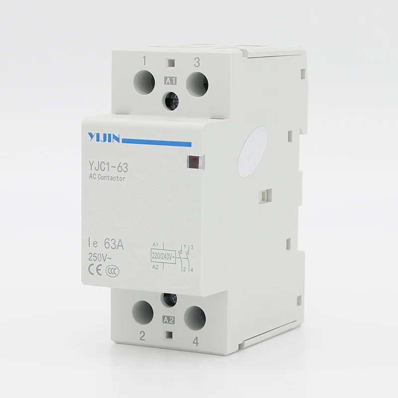
Yijin’s live contactor hub lists five modular AC contactors: YJC1-63 in 1P, 2P, and 4P, plus YJC-1-25 in 2P and 4P. There is no live Yijin split-AC outdoor definite-purpose contactor SKU on that hub.
| Sheet in hand | Honest action |
|---|---|
| Modular DIN map with A1/A2 and numbered poles | Choose a modular frame such as YJC1-63 2P Modular AC Contactor when the pole count fits; scan 1P/4P and YJC-1-25 siblings on the hub |
| Outdoor DP / split-AC L1/T1 compressor map | Keep the OEM sheet and DP outdoor hardware class; do not treat a Yijin modular DIN SKU as a drop-in outdoor replacement |
Yijin modular pages describe AC-7a remote switching language at a 230V AC 50Hz (or 60Hz) rated working voltage, TH35-7.5 rail mounting, and GB17885 / IEC1095 page statements. Those page labels are not UL Listed or NEC approval claims for the United States market.
For DIN seating and coil-voltage install checks on a modular frame, use how to install an AC contactor instead of turning this clarification into an install checklist.
FAQ
What does a split AC contactor wiring diagram usually show?
It usually shows the outdoor-unit contactor on a split-system air conditioner: line, load, and a separate coil path inside the outdoor section.
What do L1, L2, T1, and T2 mean?
L1 and L2 are incoming line terminals. T1 and T2 are the switched load terminals toward the compressor and outdoor fan.
Is the outdoor coil always 24 volts?
No. Many residential outdoor sheets use a 24 VAC control circuit, but the printed coil rating and OEM diagram decide the voltage — not a search habit.
Is a modular DIN contactor the same as an HVAC definite-purpose contactor?
No. Outdoor DP maps and modular DIN maps are different document and hardware families, even though both are contactors.
Can I use a Yijin modular contactor on my outdoor unit sheet?
Only when the sheet you hold is actually a modular DIN contact map. Yijin’s live catalogue does not list an HVAC outdoor definite-purpose contactor, so do not force-fit a modular frame onto an outdoor DP sheet.
Why might only one high-voltage leg open on my condenser contactor?
Some outdoor units use a single-pole contactor that leaves one leg continuous. Read the OEM diagram before calling that “half broken.”
Does the diagram tell me wire size and breaker size?
Usually not. OEM outdoor notes point ampacity and overcurrent protection to the unit rating plate and the qualified install path.
Are L1 and L2 still energized when the outdoor fan is off?
They can be. With the breaker or disconnect closed, line terminals may stay live even when the coil is de-energized and the outdoor fan is still.
References
- Contactor — Wikipedia
- Wiring diagram — Wikipedia
- Upgrading a single-pole contactor with a SureSwitch using a wiring diagram — HVAC School
- Question regarding L1, L2, T1 — DoItYourself.com HVAC forum
Humanizer audit: PASS
Humanizer second-pass owner: YJ-DRF-AGT-20260925-02
Humanizer second-pass note: Cut repeated “this is not…” openers; kept one outdoor-vs-modular contrast thesis; invented no UL, torque, AWG, or outdoor ampere pairing; no firsthand test claims.