 Yueqing Yijin Electronics Co., Ltd.



Solar Disconnect Switch Wiring Diagram: Land Wires Safely
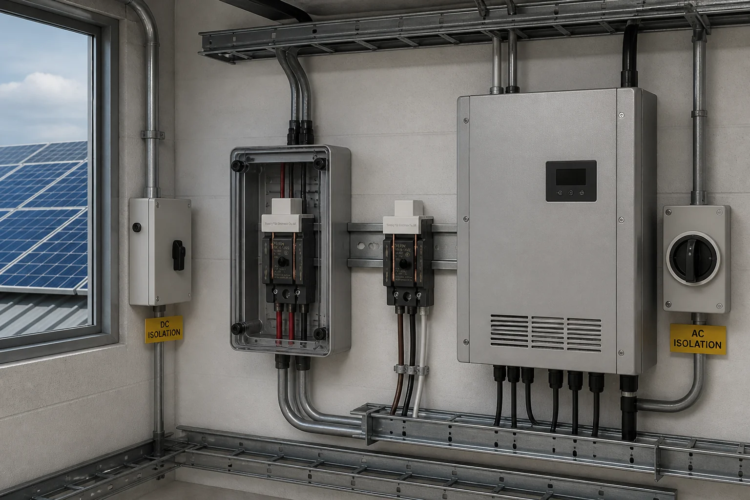
solar disconnect switch wiring diagram maps how conductors from the PV array / solar panels enter a manual isolation point and leave toward a charge controller or inverter—often with a separate solar AC disconnect after the inverter toward loads or the grid. Read the PV disconnect wiring roles, run DC isolator switch checks, apply dual-pole switching when the sheet requires it, and match a knife switch / HK18 / HD11F only when the drawing calls for protected AC-20B isolation.
What a Solar Disconnect Wiring Diagram Actually Shows
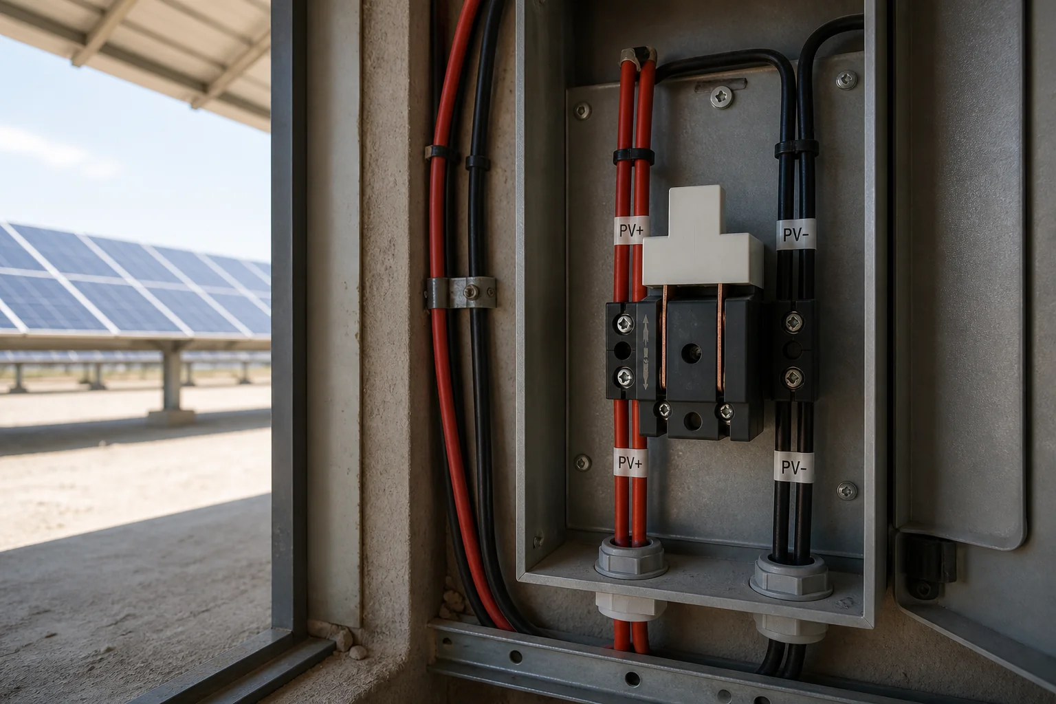
A solar disconnect wiring diagram is a connection map, not a shopping photo: it shows which conductors enter and leave a manually operated isolation point on the PV path.
On most one-line sketches you will see the array (or string) on one side of that switch and the inverter or charge controller on the other. Grid-tied drawings often add a second isolation point on the AC side after the inverter. The diagram’s job is to keep those landings unambiguous so a technician can open a defined path before service.
Treat every symbol as a decision: which side is still energized when the handle is open, how many poles move together, and whether the device is drawn as an isolator or as a load-break disconnect. If the drawing and the hardware class disagree, stop and reconcile them before you torque terminals.
| Diagram role | Typical position on the drawing | What to verify before landing wires |
|---|---|---|
| DC / PV disconnect | Between array conductors and inverter or charge controller | Voltage class, pole count, and whether both + and − open together |
| AC disconnect | After the inverter toward loads or the utility path | That you are not treating an array-side isolator as the grid disconnect |
| Isolation / knife point | Protected indoor or covered location on many IEC drawings | Off-load duty and enclosure notes match the install environment |
DC vs AC Disconnect Roles Before You Land Wires
DC disconnects isolate the array path; AC disconnects isolate after the inverter toward the building or utility path—landing the wrong side first is the most common diagram error.
A DC disconnect sits on the direct-current conductors so the inverter or charge controller can be separated from modules that still produce voltage in daylight. An AC disconnect sits on the alternating-current side so workers or utilities can open the path after conversion. Education summaries of PV practice often describe both roles on grid-tied systems; a camper or shed DC-only map may show only the array-side open.
When you read the sheet, mark “DC” and “AC” in the margin before you strip insulation. If the project is grid-tied, expect interconnection and permit context beyond a single switch sketch—the disconnect is one isolation means, not the whole interconnection package.
Pre-Wire Checks: Live Array, Load State, Reachability
Confirm the array path can be controlled, the device is used within its off-load isolation duty, and the handle stays reachable before you land conductors.
Illuminated modules can keep array conductors live even when an inverter display looks quiet, so plan an open you can prove before you touch terminations. Isolators and disconnects are generally opened after load current is already interrupted unless the device is explicitly rated for load-break duty. Keep the isolation point identifiable by position or durable marking, and place it where a worker can reach it without climbing under equipment.
Important: Source: Google AI Overview education language on PV disconnect purpose; EXPLORIST.life camper disconnect how-to (live-array caution).
Solar modules produce voltage whenever light hits them. Do not treat “the inverter is off” as proof that array conductors are safe to land.Tip: Source: EXPLORIST.life dual-pole solar disconnect wiring guide.
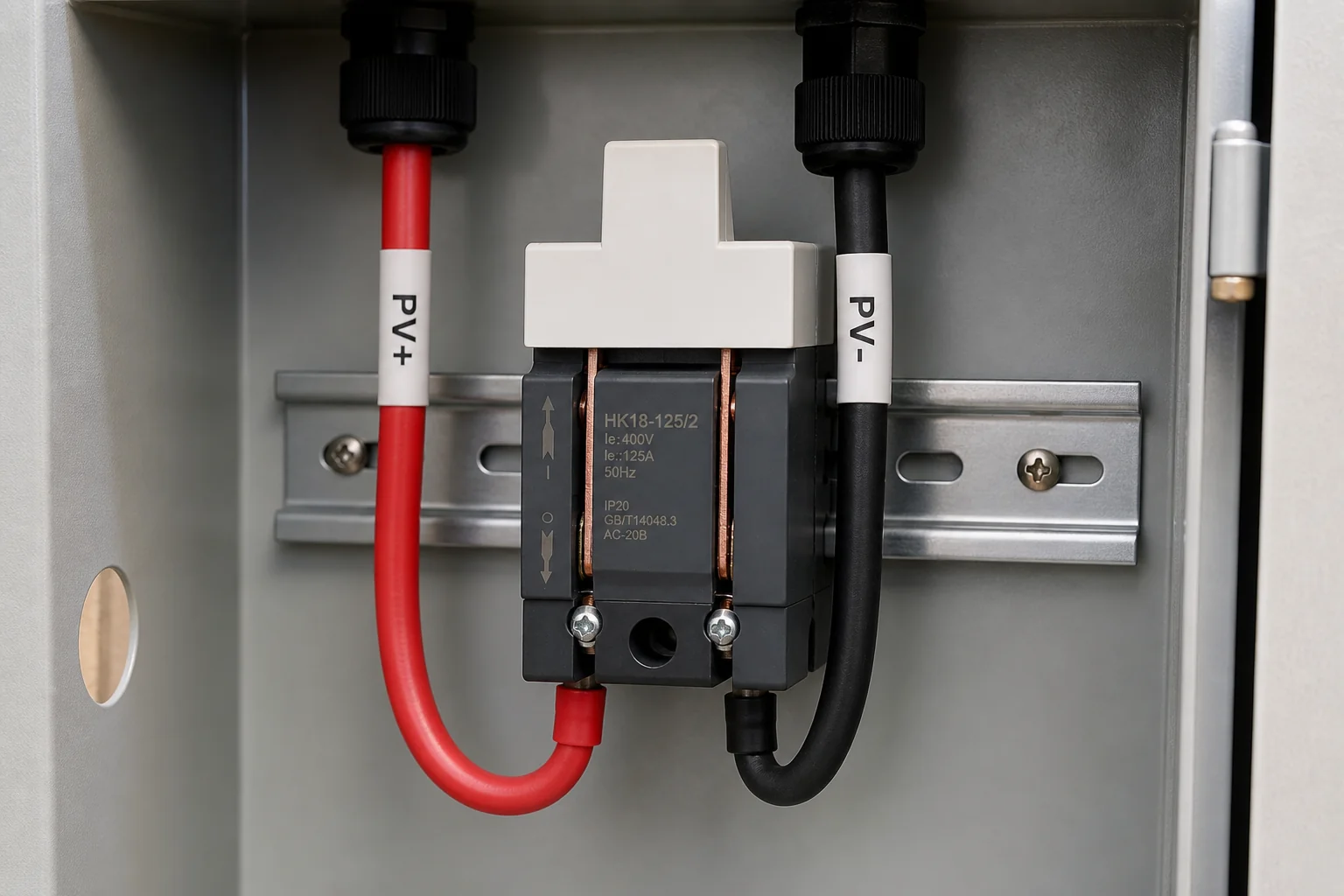
On many ungrounded DC maps, both the positive and negative conductors must open together. A single-pole open that leaves one DC leg connected does not match that diagram.
Wire Landing Map: Array → Disconnect → Controller or Inverter
Land array conductors into the disconnect first, then exit toward the charge controller or inverter—opening both poles when the map requires a dual-pole DC open.
A practical sequence used on DIY array-to-controller builds is: mount the disconnect where wire length to the controller stays short and the handle stays accessible; bring array positives and negatives into the line side; take the load-side pair onward to the controller or inverter. Field how-tos commonly finish with a continuity check after terminations so you know the handle truly opens the intended poles.
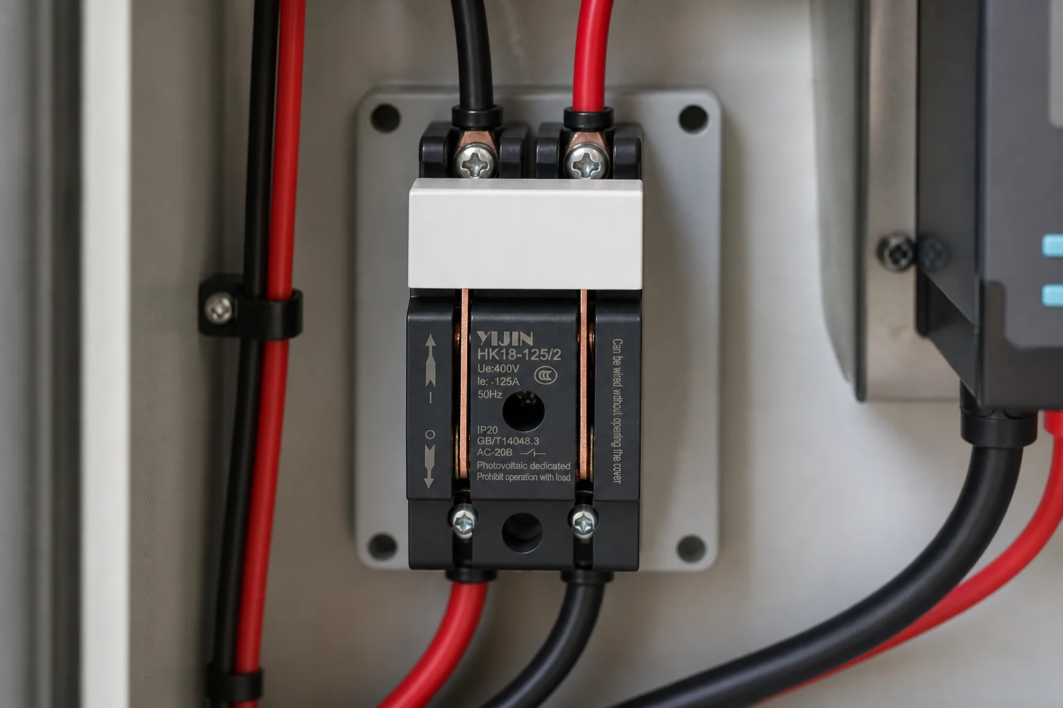
Keep glands, ferrules, and torque values aligned with the enclosure and device instructions on the drawing package. If the diagram shows two strings into a multi-pole isolator, land and test one string path at a time rather than assuming parallel landings are interchangeable.
Common Wiring-Diagram Mistakes That Keep Circuits Live
Wrong-side devices, single-pole opens on ungrounded DC, blocked handles, and category mix-ups are the mistakes that leave someone believing a circuit is open when it is not.
Shopping pages push outdoor 1000 VDC shutoffs and cabin kits that may be correct for a listed DC disconnect duty—and wrong for an IEC AC-20B knife drawn as a protected isolation point. The reverse error is equally costly: using a protected indoor knife where the drawing and AHJ expect a listed outdoor PV disconnect.
Other recurring failures:
- Treating a WiFi breaker or reclosing protector from a mixed “isolating switch” catalog as the PV disconnect on the diagram
- Mounting the open where it cannot be reached quickly from the equipment being serviced
- Skipping labels when the isolator sits remote from the gear it isolates
- Assuming a continuity test is optional after multi-pole landings
From the field: Source: Mike Holt Forum thread on NEC 440.14 disconnect location (reachability practice).
Field replies stress putting a disconnecting means where workers can reach it from the equipment that needs service—not behind a climb or a blocked porch path. Transfer that accessibility habit to PV service points even when the code article on the sheet differs.
When HK18 or HD11F Knife Isolators Fit the Diagram
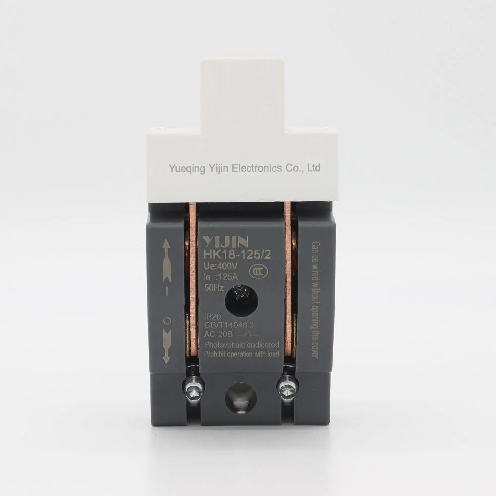
Use HK18-125 type knife switch for photovoltaic applications or HD11F-250 when the drawing calls for a protected AC-20B isolation point—not when you need a listed outdoor DC PV disconnect.
HK18 is the live PV-named knife series on Yijin’s Isolating Switch hub and appears in the New Energy solution list. The product page states AC 50 Hz circuits up to 400 V, utilisation category AC-20B, IEC 60947-3 / GB/T14048.3 alignment, infrequent manual connection/disconnection and isolation, and installation without rain or snow invasion. HD11F-250 shares the AC-20B / no-load framing with higher current options (160–250 A) and a published wiring diagram on its product page.
| Parameter | HK18-125 | HD11F-250 |
|---|---|---|
| Rated operational voltage Ue | up to 400 V AC | 400 V AC |
| Frequency | 50 Hz | 50 Hz |
| Utilisation category | AC-20B | AC-20B |
| Impulse withstand Uimp | 6 kV | 8 kV |
| Current options (page) | up to 125 A class | 160 / 180 / 200 / 225 / 250 A |
| Install note | no rain or snow invasion | no rain or snow invasion |
| Standards named on page | IEC60947-3 / GB/T14048.3 | IEC60947-3 / GB/T14048.3 |
Impulse withstand on the HK18-125 page is 6 kV; on the HD11F-250 page it is 8 kV. These SKUs fit diagrams that need a protected, infrequent, no-load isolation point on an AC distribution or control path adjacent to PV equipment. They are not evidenced here as UL Listed outdoor PV DC disconnects, NEC-listed string combiner substitutes, or on-load break devices. If your one-line shows a rooftop IP-rated DC isolator or a utility AC disconnect, select hardware that matches that duty—or ask engineering—rather than stretching the knife page beyond its facts. Browse the isolating-switch family when you need related form factors; contact the factory only after the diagram duty is clear.
FAQ
Is a solar disconnect switch required?
Education summaries of PV practice treat a readily accessible disconnecting means for PV system conductors as a normal code expectation (often discussed with NEC 690.13 language on education pages). Confirm the rule with your AHJ and design package; Yijin devices are not presented here as NEC-compliant listings.
Should the PV array DC isolator be on or off?
Open it (OFF) when you need the array path isolated for landing wires or service. Leave it closed (ON) when the system is intended to produce and the rest of the design says the path should be continuous.
How do I disconnect solar panels from the charge controller?
Open the DC disconnect drawn between the array and the controller, then verify the open before you touch controller terminals. Remember the array can still be live upstream of that open in daylight.
What are the NEC requirements for solar disconnects?
Code education points to PV disconnecting means that are readily accessible for the conductors involved. Use the adopted code edition, utility interconnection rules, and a qualified designer—do not treat a product catalog as a code opinion.
What to disconnect first, solar panel or battery?
Follow the equipment manufacturer’s sequence for that inverter or controller. As a wiring caution independent of brand myths: treat illuminated array conductors as energized until you have a proven open on the drawn disconnect.
How do I disconnect my solar panels from the grid?
That is usually an AC-side action after the inverter—service disconnects, inverter AC breakers, or utility-required AC disconnects—not the DC array isolator alone.
Do I need both AC and DC disconnects?
Many grid-tied one-lines show both roles. Off-grid DC-only maps may show only the array-side open. Match the drawing and the interconnection agreement rather than copying a camper blog onto a utility project.
Can an AC-20B knife switch be my outdoor PV DC disconnect?
Not on the HK18/HD11F product-page evidence in this package. Those pages describe AC-20B isolation with no rain/snow invasion install notes. Outdoor listed DC PV disconnect duty is a different hardware class.
References
- Disconnector — Wikipedia — isolator/disconnect as off-load isolation device versus circuit breakers.
- Photovoltaic system — Wikipedia — array DC path into inverters and grid-connected architectures.
- Lockout-tagout — Wikipedia — energy-isolating devices in hazardous-energy control practice.
- Camper Van Electrical – Adding Solar — Build A Green RV — DIY language for array, disconnect, and charge-controller wire path.
- Electrician Talk — Does an AC unit need a disconnect? — field emphasis on reachable disconnecting means near equipment being serviced.