 Yueqing Yijin Electronics Co., Ltd.




AC Contactor L1 L2 T1 T2: How Line Differs From Load
AC contactor L1 L2 T1 T2 labels separate the line side from the load side on the power poles. L1 and L2 take supply; T1 and T2 feed the load after the contacts close; the coil uses its own Us control circuit. This page maps contactor terminals L1 T1 as a line vs load contactor problem, keeps AC contactor coil terminals off the power poles, flags single-pole shunt traps common on US HVAC gear, then shows how a modular DIN-rail frame still fits when it does not print the same L/T letters.
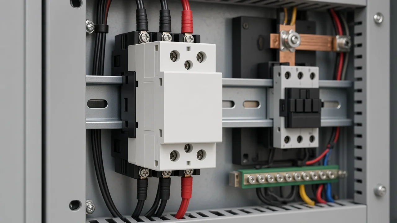
L1 and L2 mark the line side
L1 and L2 are the line terminals—the supply side of the power poles on common AC contactor labeling.
In US single-phase HVAC language, those screws often take the two hot legs from the outdoor disconnect or feeder. The “L” mark means line, not “left,” and L2 is not automatically a neutral. On a three-phase industrial frame the same idea extends to L3.
With the disconnect closed, line terminals can stay energized even while the coil is off. That is why a tech can measure voltage on the bottom (or top) row before the contactor ever clicks.
Tip: If you still read line voltage on the contactor with the outdoor disconnect closed and the thermostat idle, treat those screws as line-side until the molded marks say otherwise. Source: https://forum.heatinghelp.com/discussion/201542/help-identifying-contactor-terminals
Photograph the existing landings before you lift a wire. Matching L1 to the same conductor you removed beats guessing from a stock photo.
T1 and T2 mark the load side
T1 and T2 are the load terminals—the switched side that feeds the equipment after the poles close.
On a condenser, that often means the compressor and condenser fan circuit. The “T” mark means the load side of the pole, not the thermostat.
T1 pairs with L1; T2 pairs with L2. Crossing the numbers mixes the paths inside the device even when the coil still pulls in.
When the contacts are open, the load side should not be treated as a safe working surface just because the coil is quiet. Confirm zero energy with a meter after the disconnect and any upstream breaker are open.
The coil Us circuit is not on L1 or T1
The coil is a separate control circuit. Power on L1 and L2 does not pull the contactor in by itself.
US HVAC definite-purpose contactors commonly use a 24 V thermostat path on small side terminals. IEC-style modular frames print a rated control supply voltage Us for the suction coil and often mark those screws A1 and A2.
Either way, the electromagnet is not the same pair of screws as the power poles.
If L1/L2 are hot and the armature never moves, the next question is coil voltage and coil rating—not a second landing on the load side. Do not treat T1/T2 as coil taps. Some web pages swap those labels; the field practice and IEC-style marking keep power pairs and coil terminals apart.
On the YJC1-63 household modular page, the printed action band says the contactor can reliably close at any voltage within (80%–110%) Us after the coil reaches a stable thermal state in the stated ambient range, and the release voltage is neither higher than 75% Us nor lower than 20% Us.
Quote that band when you are reading a modular Us nameplate; do not assume a 24 V HVAC coil rating for that frame.
Line-to-load pairs when the coil closes
When the coil pulls in on a normally open main-pole contactor, matching line and load terminals bridge together.
| Terminal group | Common mark | Connects to | Role when coil is energized |
|---|---|---|---|
| Line | L1, L2 (L3 on 3-phase) | Supply / disconnect / feeder | Stays on the supply side of each pole |
| Load | T1, T2 (T3 on 3-phase) | Motor, heater, compressor, lighting load | Receives power through the closed pole |
| Coil | Us / A1–A2 | Control circuit | Pulls the armature; not a power pole |
IEC 60947-4-1 Annex A covers marking and identification of contactor terminals. The molded marks on the exact device still win over a generic diagram.
Physical layout varies. Some HVAC contactors bring line in at the bottom; many IEC frames put L above T. Orientation changes; the letter meaning does not.
Single-pole shunt and off-cycle heater pre-check
A single-pole HVAC contactor may switch only one leg while the other path rides a solid shunt bar.
That layout leaves one conductor tied through even when the coil drops out. Techs on Heating Help describe always-hot bottoms and warn that a true two-pole substitute is not a blind wire-for-wire swap when a crankcase heater depends on the open pole.
HVAC School documents Carrier-style heaters that sit across the open contact and backfeed through compressor windings so the heater runs only while the contactor is open. Replacing that part with a two-pole device without moving the heater feed can disable the off-cycle heat path.
Before you land wires on a replacement:
- Read every molded letter on the body—L, T, and coil marks.
- Decide whether the old part is true two-pole or one switched pole plus a shunt.
- Check whether an off-cycle heater or similar path uses the open pole.
- Keep coil conductors on the coil screws only.
- De-energize the disconnect and verify with a meter before touching line terminals.
This pre-check is about terminal identity, not a full bad-contactor diagnosis.
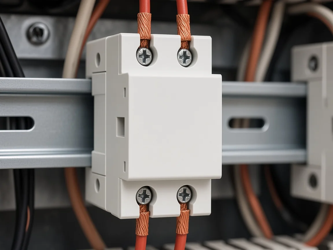
Modular power poles without invented L/T silk
A modular household AC contactor still has power poles and a separate coil circuit even when the plastic does not spell L1 or T1 the way a US definite-purpose lug block does.
US search language arrives from HVAC condenser photos. DIN-rail frames on a distribution board may show numbered poles, Us marks, or diagram callouts instead of the same raised L/T letters. Inventing L1/T1 text from a condenser stock photo and stamping it onto a modular part is how wrong landings start.
Read the marks that are actually printed on the frame and in the product drawing. Treat “line vs load vs coil” as the function map. Then match pole count: a 2P modular body switches two power paths together under one coil command.
Yijin’s contactor family lives on the contactor hub as navigation. The terminal decision stays on the model page and the equipment diagram in front of you.
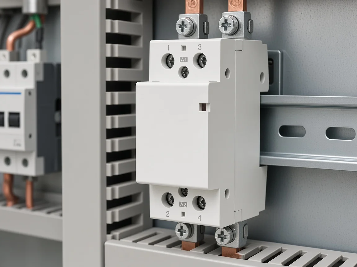
Contactor is not a circuit breaker
A contactor is an electrically operated switch for load current. It is not a circuit breaker and is not intended to interrupt short-circuit current the way a breaker is.
Keep overcurrent protection upstream. Keep a disconnecting means where the installation rules and the equipment diagram require one. The contactor’s job in this article is remote switching of the power poles under coil command—not branch protection, not lockable isolation by itself, and not a substitute for pulling the disconnect before service.
That boundary matters in US panels where buyers sometimes ask for “a contactor that also trips like a breaker.” Those are different devices.
Product fit: YJC1-63 2P modular poles and Us coil
After the L/T/coil map is clear, the YJC1-63 2P modular AC contactor fits a modular shortlist when you need a two-pole household DIN-rail frame under the printed page scope—not when you need a UL-listed definite-purpose HVAC drop-in this page does not claim.
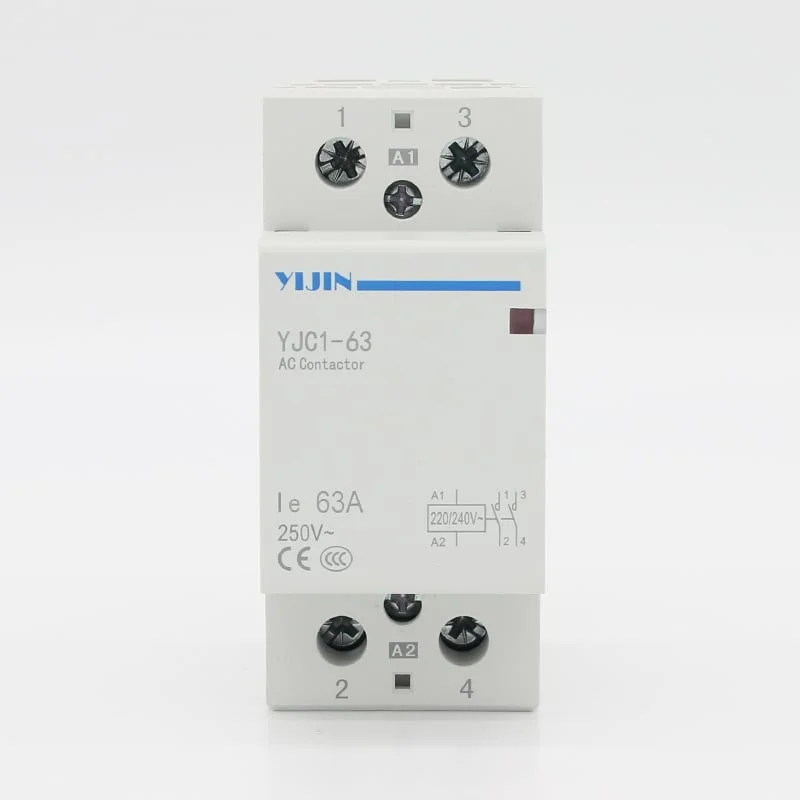
The product photo above is the first-party YJC1-63 2P frame used for this recommendation.
The live page describes a household AC contactor for power systems with AC 50 Hz (or 60 Hz) and a rated working-voltage context of 230 V. Under the AC-7a usage category it is used as a remote switch and main-circuit control in circuits with rated working voltage up to 230 V and rated working current of 63 A on that table line.
The page states compliance with GB17885 and IEC1095 standards. That is first-party page language. It is not a UL Listed claim and not an NEC approval statement for US condenser replacements.
Installation method on the page is the TH35-7.5 top-hat rail. Conventional products are normally open; normally closed versions are noted as customizable on the page.
| YJC1-63 2P printed line | Honest use in this terminal map |
|---|---|
| Household modular AC contactor, 2P | Two power poles under one coil command |
| AC 50/60 Hz, 230 V working-voltage context | Match the board voltage language on the sheet |
| AC-7a remote / main control | Switching duty on the page—not breaker duty |
| Us pickup (80%–110%); release ≤75% Us and ≥20% Us | Coil circuit sizing and control supply check |
| TH35-7.5 rail | DIN-rail board fit |
| Mechanical ≥1,000,000 cycles; electrical ≥100,000 | Page endurance wording only |
| GB17885 / IEC1095 page statement | Standards named on the sheet—not UL |
Recommend this product when the reader already understands line vs load vs coil, needs both poles switched on a modular board, and accepts the printed 230 V / AC-7a / Us scope. Do not recommend it as a silent swap for a 24 V definite-purpose HVAC contactor, as a short-circuit protective device, or with invented L1/T1 silkscreen the page body does not print.
Browse the contactor hub only after the model table matches. The hub is navigation. The terminal map stays with the marks on the part.
FAQ
What do L1 and L2 mean on an AC contactor?
They mark the line (supply) terminals on common contactor labeling. Confirm the molded letters on the exact device.
What do T1 and T2 mean on an AC contactor?
They mark the load (switched) terminals that feed the equipment when the poles close. T1 pairs with L1; T2 pairs with L2.
Why won’t the contactor pull in if L1 and L2 are hot?
Because the coil is a separate control circuit. Line voltage on the power poles does not replace Us (or the HVAC 24 V coil path) on the coil terminals.
Can I land supply on the T side instead of L?
Some field notes say the contacts can still close if line and load are reversed, but that moves wear and confuses later service. Follow the molded L/T marks and the equipment diagram.
What is different about a single-pole HVAC contactor?
One pole switches; the other path may be a solid shunt. One leg can stay tied through when the coil drops out, and some crankcase heaters depend on that topology.
Are A1 and A2 the same as L1 and T1?
No. A1 and A2 (or other Us coil marks) belong to the control electromagnet. L1 and T1 belong to a power pole pair.
Is an AC contactor a circuit breaker?
No. A contactor switches load under coil command. Short-circuit interruption belongs to a protective device selected for that duty.
How does YJC1-63 2P map if it doesn’t print L1/T1 text?
Read the printed power-pole and Us marks on that modular frame. Use the L/T function map from this article without inventing silkscreen letters the product page does not show.